Straight-line roots pump

A kind of Roots pump, in-line technology, applied in the field of in-line Roots pumps, can solve the problems of difficult processing, failure to realize the application of large and medium-sized Roots pumps, burnt motors, etc., and achieve the effect of reducing oil and gas pollution

Pending Publication Date: 2022-04-12
LANZHOU INST OF PHYSICS CHINESE ACADEMY OF SPACE TECH
View PDF0 Cites 1 Cited by
  • Summary
  • Abstract
  • Description
  • Claims
  • Application Information

AI Technical Summary

Problems solved by technology

[0003] However, when the gas pressure is high, a large amount of gas accumulates at the outlet of the pump body during the high-speed operation of the Roots pump rotor, causing the pressure at the outlet to rise sharply and the temperature to rise. The high-temperature gas will cause the rotor to The thermal expansion effect causes the gap between the active rotor and the driven rotor, and between the rotor and the cavity to become smaller, which further intensifies the temperature rise effect, and finally causes collisions between the rotors or between the rotor and the cavity. The rotor will be damaged, and the motor will be burned directly, which will cause irreversible damage to the Roots pump.
Therefore, in the vacuum unit, the Roots pump cannot operate independently, and must have the cooperation of the backing pump to work normally. In the backing pump that can be equipped with the Roots pump, oil pumps such as rotary vane pumps and slide valve pumps are usually used. It is impossible to realize the real oil-free operation of the Roots pump unit
Although the small Roots pumps on the market can directly operate under atmospheric pressure through the form of multi-stage rotors, due to the influence of extreme pressure, especially the difficulty of processing and high cost, this structural form is involved in It cannot be applied to large and medium-sized Roots pumps for large-scale applications such as semiconductors, chemicals, and metallurgy.

Method used


Image

  • Straight-line roots pump
  • Straight-line roots pump
  • Straight-line roots pump

Examples


Embodiment Construction

[0023] In order to enable those skilled in the art to better understand the solution of the present application, the technical solution in the embodiment of the application will be clearly and completely described below in conjunction with the accompanying drawings in the embodiment of the application. Obviously, the described embodiment is only It is an embodiment of a part of the application, but not all of the embodiments. Based on the embodiments in this application, all other embodiments obtained by persons of ordinary skill in the art without creative efforts shall fall within the scope of protection of this application.

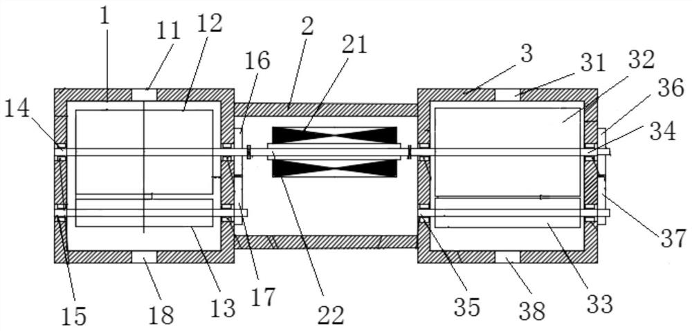
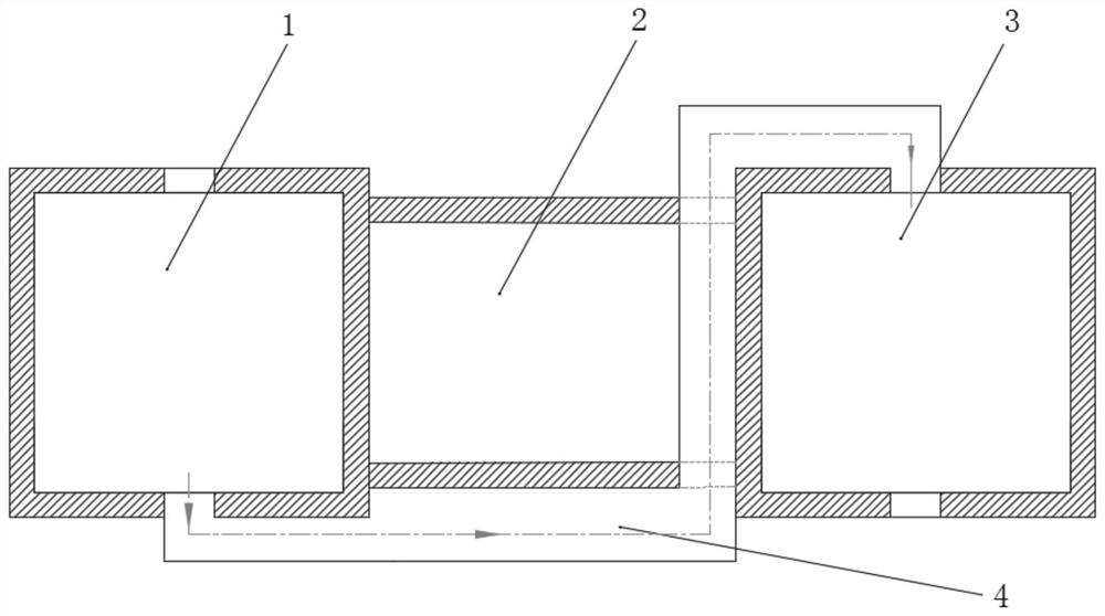
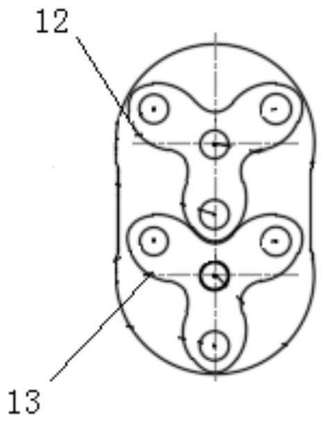
[0024] like Figure 1-2 As shown, the application provides an in-line Roots pump, including a first cavity 1, a second cavity 2 and a third cavity 3 connected in sequence, the first cavity 1, the second cavity 2 and the A sealing rubber ring is provided between the third chambers 3 , and the first air outlet 18 of the first chamber 1 communicates with...


PUM


Abstract

The invention relates to the technical field of vacuum, in particular to a straight-line roots pump which comprises a first cavity, a second cavity and a third cavity which are sequentially connected, sealing rubber rings are arranged among the first cavity, the second cavity and the third cavity, and a first air outlet of the first cavity is communicated with a second air inlet of the third cavity through a connecting pipe. The motor drives the two evacuation cavities with different compression ratios to compress and evacuate gas in a segmented mode, two-stage compression is adopted to achieve gas extraction of the roots pump under the atmospheric pressure, the problem that a rotary vane pump, a slide valve pump and other preceding-stage oil pumps need to be arranged in the operation process of a conventional roots pump is solved, oil gas pollution to the vacuum environment is reduced, and the service life of the roots pump is prolonged. The oil-free clean space of the roots pump unit is really realized, and a clean vacuum environment is provided for the roots pump unit, particularly a high-pumping-speed roots pump unit.

Description

technical field [0001] The present application relates to the field of vacuum technology, in particular, to an in-line Roots pump. Background technique [0002] Roots vacuum pump (Roots pump for short) is a double-rotor volumetric vacuum pump. In the pump chamber, the two rotors are installed on a pair of parallel shafts perpendicular to each other. Since there is no friction in the Roots pump chamber, the rotors can move at high speed. It rotates, and there is no lubricating oil in the chamber, which can realize an oil-free and clean pumping process, especially with a large pumping speed in the inlet pressure range of 1-100Pa, and is suitable for vacuum systems that require a high pumping speed at an inlet pressure of 0.01-100Pa. Use, such as vacuum smelting exhaust, vacuum coating equipment pre-pumping, vacuum distillation, concentration, drying and other processes in food, chemical, pharmaceutical, textile and other industries. In addition, the production of semiconducto...

Claims


Application Information

Patent Timeline
IPC IPC(8): F04C23/02F04C23/00F04C18/12F04C25/02F04C29/00
Inventor 李小金李正清刘筱文王毅蔡宇宏韩仙虎
Owner LANZHOU INST OF PHYSICS CHINESE ACADEMY OF SPACE TECH
Why Eureka
Try Eureka