Textile yarn automatic stopping mechanism
A technology for spinning yarn and stopping mechanism, which is applied to the field of automatic yarn stopping mechanism for textile yarn, can solve the problems affecting the quality of the reeling yarn of the device, yarn breakage, yarn knotting, etc., so as to ensure the quality of the reeling yarn and reduce the frictional force. , Guaranteed quality effect
- Summary
- Abstract
- Description
- Claims
- Application Information
AI Technical Summary
Problems solved by technology
Method used
Image

Examples
Embodiment 1
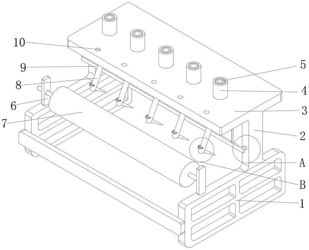
[0027] see figure 1 , the present invention provides a technical solution: an automatic thread stop mechanism for textile yarns, comprising a base 1, the upper surface of the base 1 is fixedly connected with a first support frame 2, and the upper surface of the first support frame 2 is fixedly connected with a placement plate 3. Further, through the setting of the first support frame 2, the placement plate 3 is supported, the surface of the placement plate 3 is fixedly connected with the fixed cylinder 5, and the surface of the fixed cylinder 5 is movably socketed with the wire cylinder 4. Through the setting of the fixed cylinder 5, Fixing the bobbins 4 avoids excessive swaying of the bobbins 4 when the yarns on the bobbins 4 are pulled out, thereby avoiding the mutual entanglement of the yarns on two adjacent bobbins 4 The situation ensures the stability of the device. The surface of the placement plate 3 is provided with a through hole 10, and the through hole 10 is arrange...
Embodiment 2
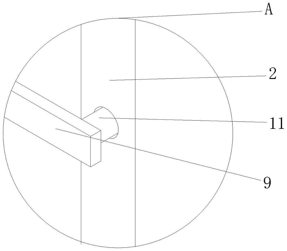
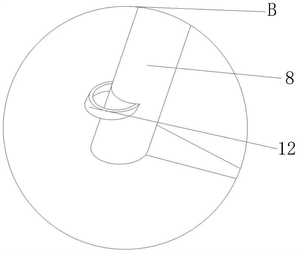
[0031] see Figure 2-5 , on the basis of Embodiment 1, the bottom of the placement plate 3 is provided with an arc-shaped first connection groove 14, the inner wall of the first connection groove 14 is provided with a stop mechanism, the stop mechanism includes a rotating disk 13, and the surface of the rotating disk 13 Slidingly connected with the inner wall of the first connection groove 14, the lower side of the rotating disk 13 is fixedly connected with an "L" knocking rod 8, the front end of the knocking rod 8 is tapered, and the surface of the knocking rod 8 is fixedly connected with a fixed Ring 12, the rear side of the first support frame 2 is provided with a control switch 11, and the control switch 11 controls the start and stop of the external motor.
[0032] The bottom of the placement plate 3 is provided with a second connecting groove 15, the inwall of the second connecting groove 15 is slidably connected with a connecting rod 19, the left and right sides of the ...
Embodiment 3
[0036] see Image 6 , on the basis of Embodiments 1 and 2, the surface of the second support frame 6 is provided with a second rotating groove 24, the surface of the yarn frame 7 is rotationally connected with the inner wall of the second rotating groove 24, and the inner wall of the second rotating groove 24 is provided with There is a "7"-shaped draw-in groove 20, and the surface of the yarn frame 7 is provided with a placement groove 23, and the inner wall of the placement groove 23 is slidably connected with a clamping rod 21, and the surface of the clamping rod 21 is slidably connected with the inner wall of the clamping groove 20, and the clamping rod A spring 22 is fixedly connected to an end of the spring 21 away from the clamping groove 20 , and an end of the spring 22 away from the clamping rod 21 is fixedly connected to the inner wall of the placement groove 23 .
[0037] When the yarn frame 7 rotates, the clamping rod 21 slides along the bottom of the clamping groo...
PUM
 Abstract
Description
Claims
Application Information
 - Generate Ideas
- Intellectual Property
- Life Sciences
- Materials
- Tech Scout
- Unparalleled Data Quality
- Higher Quality Content
- 60% Fewer Hallucinations
Browse by: Latest US Patents, China's latest patents, Technical Efficacy Thesaurus, Application Domain, Technology Topic, Popular Technical Reports.
© 2025 PatSnap. All rights reserved.Legal|Privacy policy|Modern Slavery Act Transparency Statement|Sitemap|About US| Contact US: help@patsnap.com