
Unmanned aerial vehicle surveying and mapping device

A surveying and mapping device and unmanned aerial vehicle technology, applied in the field of surveying and mapping, can solve problems such as inconvenient maintenance and disassembly, easy accumulation of dust on the camera, and difficulty in continuous and clear camera surveying and mapping of the camera, so as to improve the effect of surveying and mapping, stabilize the structure, and strengthen the stability of the connection sexual effect

Pending Publication Date: 2022-04-12
浙江四维远见信息技术股份有限公司
View PDF0 Cites 0 Cited by
  • Summary
  • Abstract
  • Description
  • Claims
  • Application Information

AI Technical Summary

Problems solved by technology

[0005] The invention provides a UAV surveying and mapping device, one of which is to have the function of protection and cleaning, and solve the problem that when the UAV is equipped with a camera for flying camera surveying and mapping, because the camera is exposed to the environment, the camera is easy to accumulate dust, which makes the camera difficult to clean. The problem of continuous and clear camera surveying and mapping; another purpose is to solve the general UAV surveying and mapping device. When installing the camera, it is often fixed by bolts and nuts, which is very inconvenient during maintenance and disassembly. In order to achieve the effect of easy installation and removal of the camera

Method used


Image

  • Unmanned aerial vehicle surveying and mapping device
  • Unmanned aerial vehicle surveying and mapping device
  • Unmanned aerial vehicle surveying and mapping device

Examples


Embodiment 1

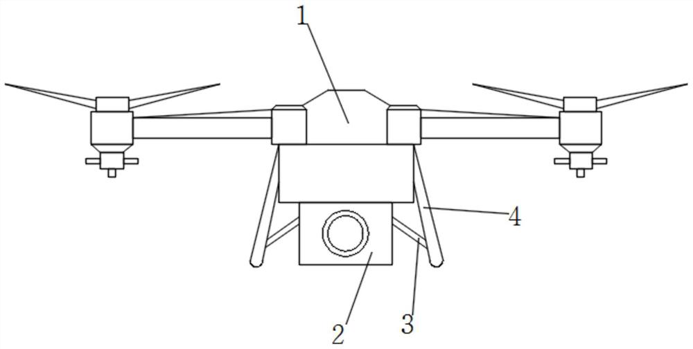
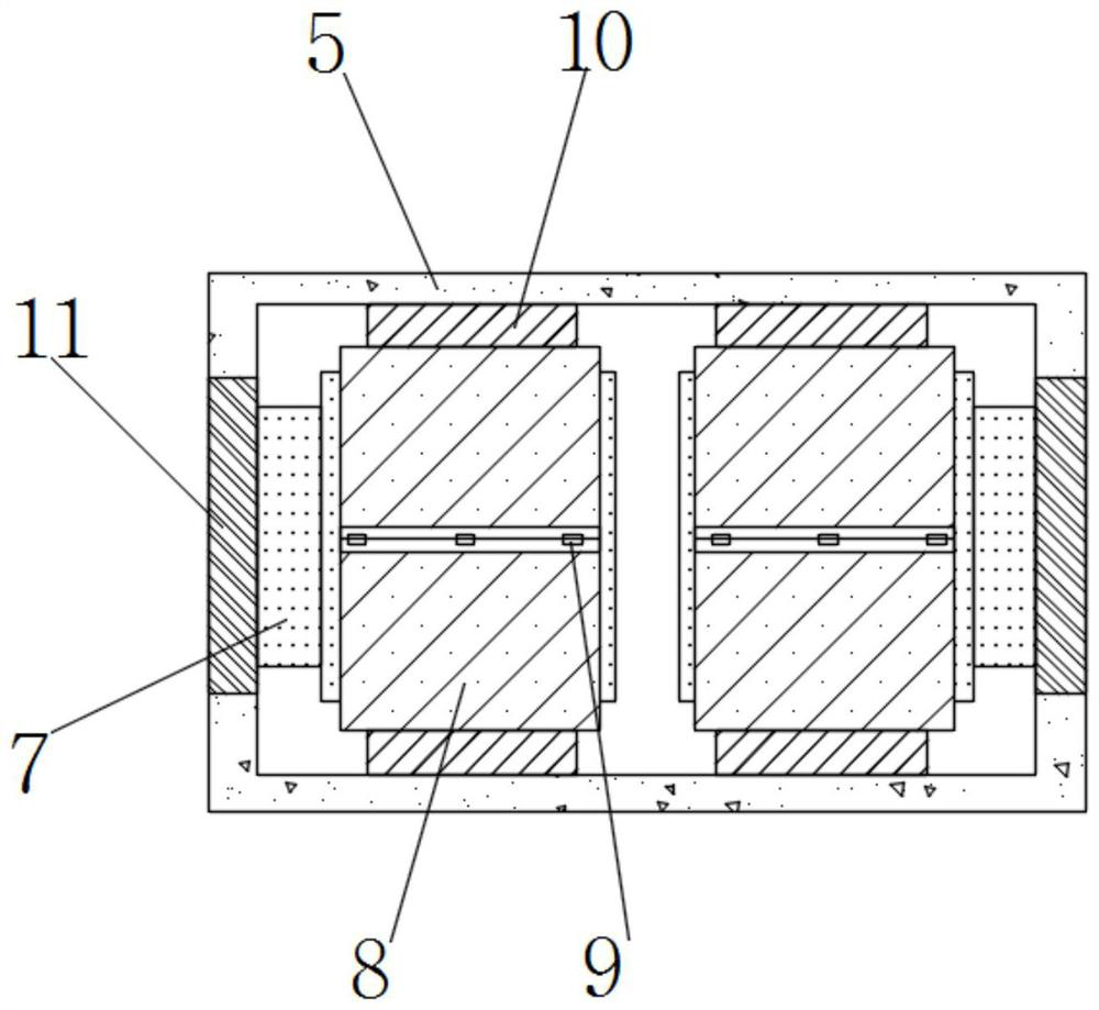
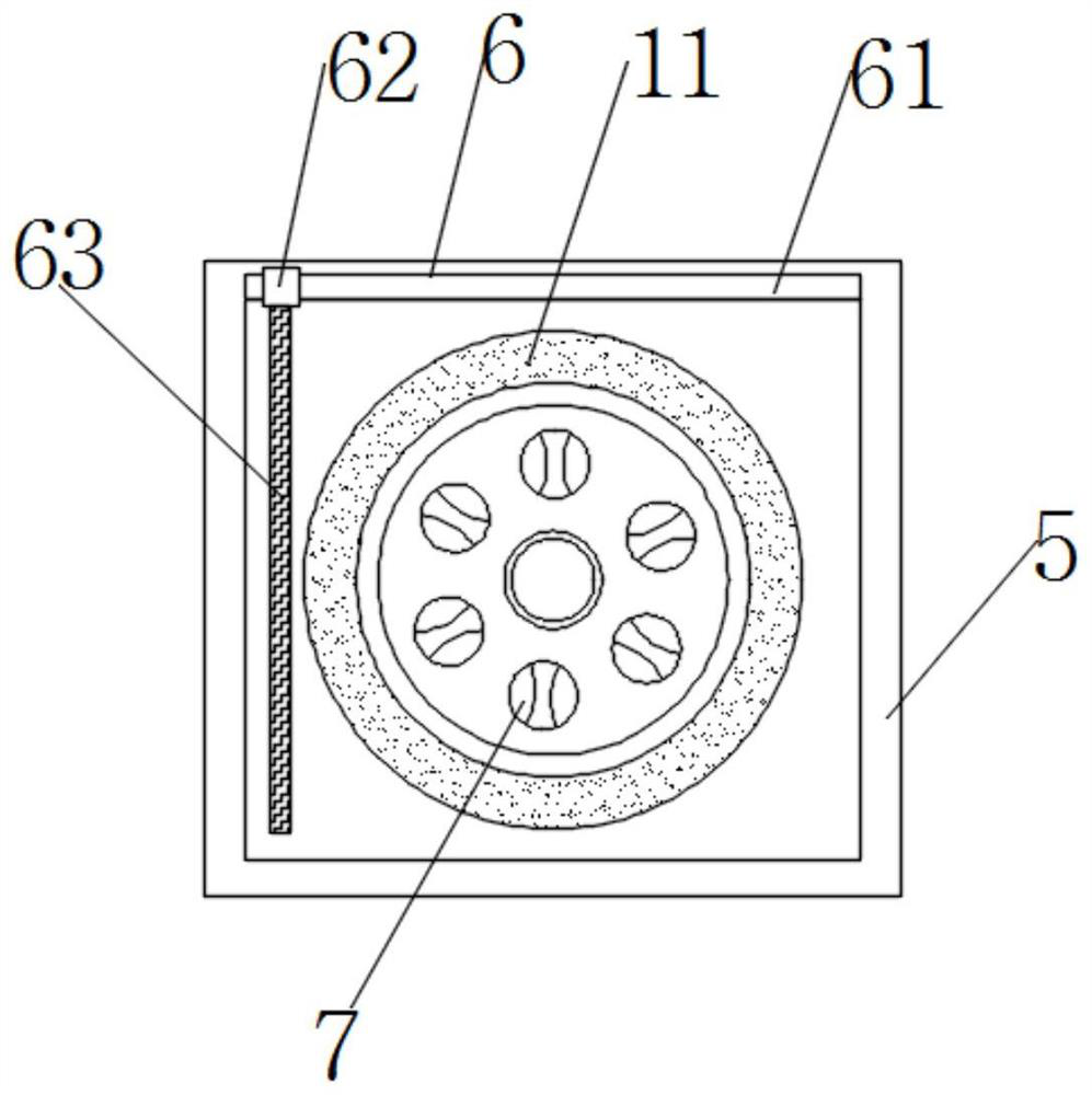
[0032] Such as Figure 1-5 As shown, the present invention provides a UAV surveying and mapping device, including a UAV body 1, a surveying and mapping assembly 2 is arranged at the bottom of the UAV body 1, and a first reinforced support diagonal bar 3 is fixedly installed on the side of the surveying and mapping assembly 2 The side of the first reinforced support slant bar 3 is fixedly connected with the second reinforced support slant bar 4, the surveying and mapping assembly 2 includes a protective box 5, the interior of the protective box 5 is provided with a surveying and mapping camera 7, and the side of the protective box 5 is provided with a cleaning assembly 6 , the outside of the surveying and mapping camera 7 is provided with a stabilizing sleeve 8, and the surface of the stabilizing sleeve 8 is provided with a clamping assembly 9. By setting the surveying and mapping assembly 2, the first reinforced support slant bar 3 and the second reinforced support slant bar 4 ...

Embodiment 2

[0034] Such as Figure 1-5 As shown, on the basis of Embodiment 1, the present invention provides a technical solution: preferably, the cleaning assembly 6 includes an electric slide bar 61, and the electric slide bar 61 is fixedly installed on the side of the protective box 5, and the outside of the electric slide bar 61 An electric slider 62 is movable, and one end of the electric slider 62 is provided with a cleaning brush 63. By setting the cleaning assembly 6, the electric slider 61 is started to drive the electric slider 62 to slide on its surface, so that the cleaning brush 63 is in high definition. The surface of the transparent anti-collision glass 11 slides to clean the surface of the high-definition transparent anti-collision glass 11 to prevent dust from being adsorbed on the surface of the high-definition transparent anti-collision glass 11 in the process of surveying and mapping, which affects the clarity of surveying and mapping, making surveying and mapping The...

Embodiment 3

[0036] Such as Figure 1-5As shown, on the basis of Embodiment 1, the present invention provides a technical solution: preferably, the inside of the stabilizing sleeve 8 is fixedly equipped with an elastic column 12, and the upper and lower ends of the stabilizing sleeve 8 are fixedly equipped with a fixed plate 10, stabilizing The right side of cover 8 is fixedly installed with first elastic band 13, and the bottom of first elastic band 13 is provided with clamping assembly 9, and the bottom of clamping assembly 9 is provided with second elastic band 14, and second elastic band 14 is fixedly installed on One end of the stabilizing sleeve 8, the clamping assembly 9 includes a clamping sleeve 91, and the inside of the clamping sleeve 91 is provided with a clamping groove 92, and the inner wall of the clamping groove 92 is movably installed with a limit tilting rod 95, and the bottom of the first elastic band 13 is fixedly installed Anti-skid hand-held piece 93 is arranged, and ...


PUM


Abstract

The invention discloses an unmanned aerial vehicle surveying and mapping device, and relates to the technical field of surveying and mapping, the unmanned aerial vehicle surveying and mapping device comprises an unmanned aerial vehicle body, the bottom of the unmanned aerial vehicle body is provided with a surveying and mapping assembly, the side surface of the surveying and mapping assembly is fixedly provided with a first reinforcing supporting inclined rod, and the side surface of the first reinforcing supporting inclined rod is fixedly connected with a second reinforcing supporting inclined rod; a surveying and mapping camera is arranged in the protection box, and a cleaning assembly is arranged on the side face of the protection box. According to the high-definition transparent anti-collision glass surveying and mapping device, through cooperation of the surveying and mapping assembly, the first reinforcing supporting inclined rod and the second reinforcing supporting inclined rod, the topographic appearance in the front and back aspects can be surveyed and mapped, the surveying and mapping range is widened, stability is high, dust on the surface of high-definition transparent anti-collision glass is cleaned through the cleaning assembly, and the practicability is high. Dust is prevented from being adsorbed on the surface of the high-definition transparent anti-collision glass in the surveying and mapping process to influence the surveying and mapping definition, so that the surveying and mapping camera can shoot and map clearly for a long time, and the surveying and mapping effect is improved.

Description

technical field [0001] The invention relates to the technical field of surveying and mapping, in particular to an unmanned aerial vehicle surveying and mapping device. Background technique [0002] An unmanned aerial vehicle is an unmanned aircraft operated by radio remote control equipment and its own program control device, or operated completely or intermittently autonomously by an on-board computer. From a technical point of view, it can be divided into: unmanned fixed-wing aircraft, unmanned vertical take-off and landing aircraft, unmanned airship, unmanned helicopter, unmanned multi-rotor aircraft, unmanned parawing aircraft, etc. Compared with manned aircraft, it has the advantages of small size, low cost, convenient use, low requirements for combat environment, and strong battlefield survivability. With the development of UAV remote sensing technology, the wide application of image acquisition, and the UAV aerial photogrammetry system applied to aerial photogrammetr...

Claims


Application Information

Patent Timeline
Patent Type & Authority Applications(China)
IPC IPC(8): B64D47/08B64C39/02B08B1/00
Inventor 李水平董俊红左建章杨铁利
Owner 浙江四维远见信息技术股份有限公司
Learn More