
Textile fabric printing machine

A technology for textile fabrics and printing machines, applied in printing machines, flatbed printing machines, printing and other directions, can solve the problems of inability to quickly change printing patterns, inconvenience for users, time-consuming and labor-intensive, etc., to increase convenience, save time, The effect of reducing the cost of use

Pending Publication Date: 2022-04-12
金湛
View PDF8 Cites 1 Cited by
  • Summary
  • Abstract
  • Description
  • Claims
  • Application Information

AI Technical Summary

Problems solved by technology

[0004] The above-mentioned patent solves the problem that the existing printing machine device cannot quickly change the printing pattern by setting the first side plate, the second side plate, the rotating shaft, the quick-detachable side plate, the inflatable shaft, the replaceable carved nitrile rubber sleeve and the eccentric shaft. However, because the above-mentioned device needs to go through a series of disassembly and installation operations when replacing the engraved nitrile rubber sleeve, the process is complicated, time-consuming and laborious, and dyes will remain on the outer surface of the engraved nitrile rubber sleeve. Inevitably stained with dye, causing inconvenience to users

Method used


Image

  • Textile fabric printing machine
  • Textile fabric printing machine
  • Textile fabric printing machine

Examples


Embodiment Construction

[0031] The following will be combined with the present invention to realize some embodiments of the present invention, rather than all embodiments. Based on the embodiments of the present invention, all other embodiments obtained by persons of ordinary skill in the art without making creative efforts belong to the protection scope of the present invention.

[0032] In describing the present invention, it is to be understood that the terms "center", "longitudinal", "transverse", "length", "width", "thickness", "upper", "lower", "front", " Back", "Left", "Right", "Vertical", "Horizontal", "Top", "Bottom", "Inner", "Outer", "Clockwise", "Counterclockwise", etc. or The positional relationship is based on the orientation or positional relationship shown in the drawings, which is only for the convenience of describing the present invention and simplifying the description, rather than indicating or implying that the referred device or element must have a specific orientation, be cons...


PUM


Abstract

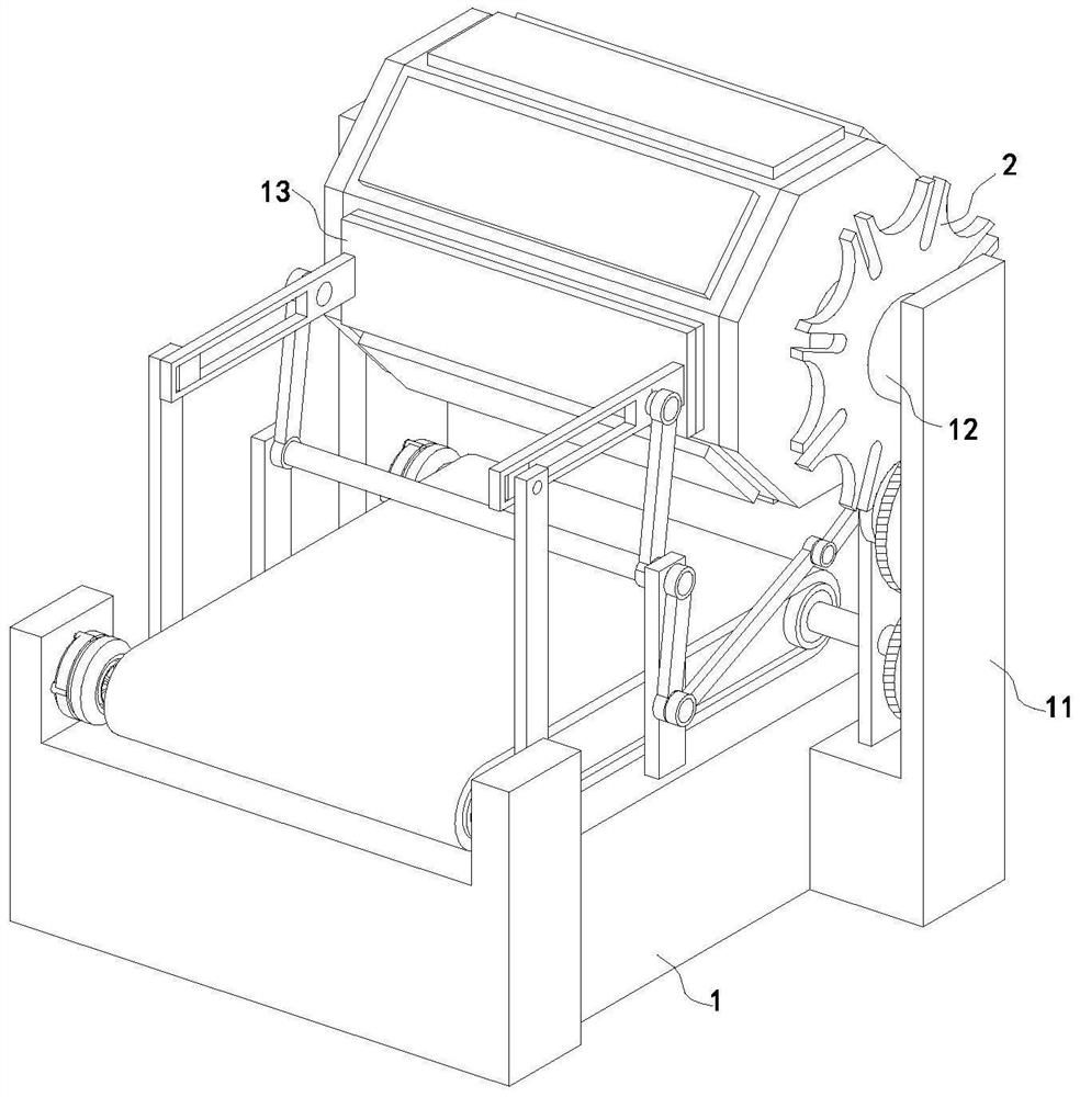
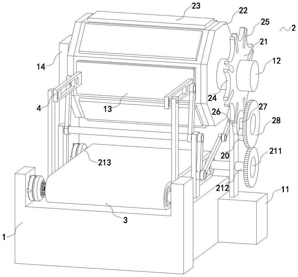
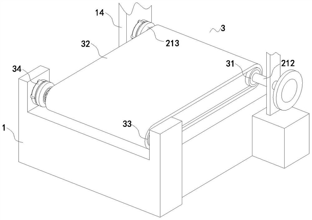
The invention relates to the technical field of printing machines, in particular to a textile fabric printing machine which comprises a fixing seat, a first fixing frame is fixedly connected to the rear end of the outer surface of the right side of the fixing seat, a connecting roller is rotatably connected to the upper end of the outer surface of the left side of the first fixing frame through a bearing, and an adjusting mechanism is fixedly connected to the annular outer surface of the connecting roller. And the adjusting mechanism comprises an adjusting disc, a movable cylinder, a bottom plate, a strip-shaped groove, a connecting block, a driven fluted disc, a first connecting rod, a driving rod, a driving fluted disc, a rotating rod and a first driving motor. The adjusting mechanism is arranged, the first driving motor is used for driving the movable barrel to rotate, then the multiple sets of bottom plates rotate, and therefore the purpose of replacing printed patterns is achieved, operation is easy, complicated mounting and dismounting operation is not needed, time is saved, hands do not need to make contact with the bottom plates, and the working efficiency is improved. And the situation that the hands of an operator are contaminated by residual fuel is avoided, and the use convenience of the device is improved.

Description

technical field [0001] The invention relates to the technical field of printing machines, in particular to a printing machine for textile fabrics. Background technique [0002] The printing machine is suitable for printing on various materials. After refitting, the application range of the printing machine is wider, no longer limited to paper printing. The printing machine is mainly divided into thermal transfer printing machine, digital printing machine, flat screen printing machine and rotary screen printing machine, The transfer printing technology is a new type of printing method. Its main feature is energy saving and environmental protection. Pressure, heating) or chemical methods (such as: additive reaction) to transfer the pattern of the dye on the transfer plate to the printed fabric. [0003] The existing patent (application number: CN202020940664.7) is a printing machine device capable of quickly changing printing patterns, including a first side plate, and a seco...

Claims


Application Information

Patent Timeline
Patent Type & Authority Applications(China)
IPC IPC(8): B41F1/08B41F1/38B41F1/26
Inventor 金湛李豪杰
Owner 金湛
Learn More