
Photovoltaic cell surface passivation film production equipment

A technology for production equipment and photovoltaic cells, which is applied in circuits, electrical components, and final product manufacturing. It can solve problems such as wasting manpower, reducing automated production processes, and affecting production efficiency, reducing labor consumption, and improving mechanization and automated production. Process, ensure stable and accurate transmission effect

Pending Publication Date: 2022-04-08
江苏龙恒新能源有限公司
View PDF1 Cites 4 Cited by
  • Summary
  • Abstract
  • Description
  • Claims
  • Application Information

AI Technical Summary

Problems solved by technology

[0006] Although this solar cell surface passivation film production equipment can complete the preparation of the tunneling oxidation passivation film and anti-reflection film with increased opening pressure, the use of Bernoulli suction cups can avoid the problem of coating scratches; at the same time, the silicon wafer positioning mechanism on the graphite plate It can reduce problems such as stuck printing, silicon wafer deformation, and high fragmentation rate. However, in order to ensure the safety of the battery panels when this production equipment is working, manual loading is required during the coating process, and the battery panels are placed on the workbench one by one. It greatly affects production efficiency, wastes manpower, and reduces the process of automated production

Method used


Image

  • Photovoltaic cell surface passivation film production equipment
  • Photovoltaic cell surface passivation film production equipment
  • Photovoltaic cell surface passivation film production equipment

Examples


Embodiment Construction

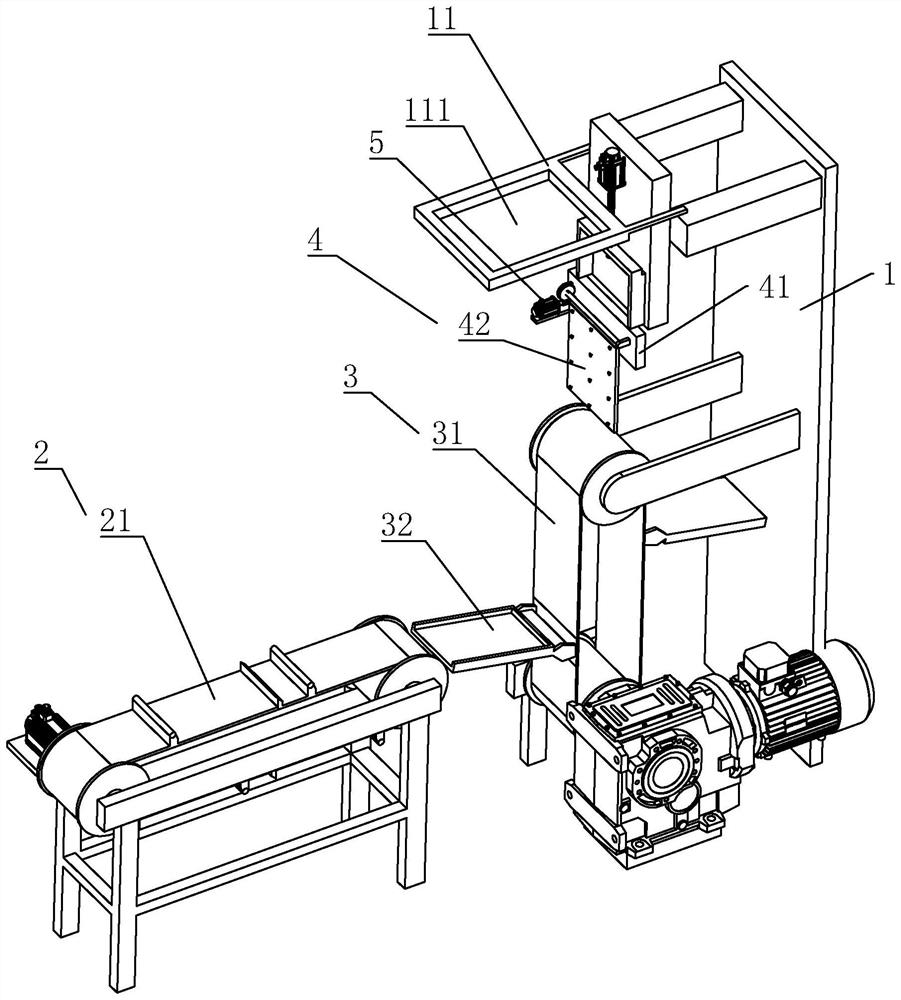
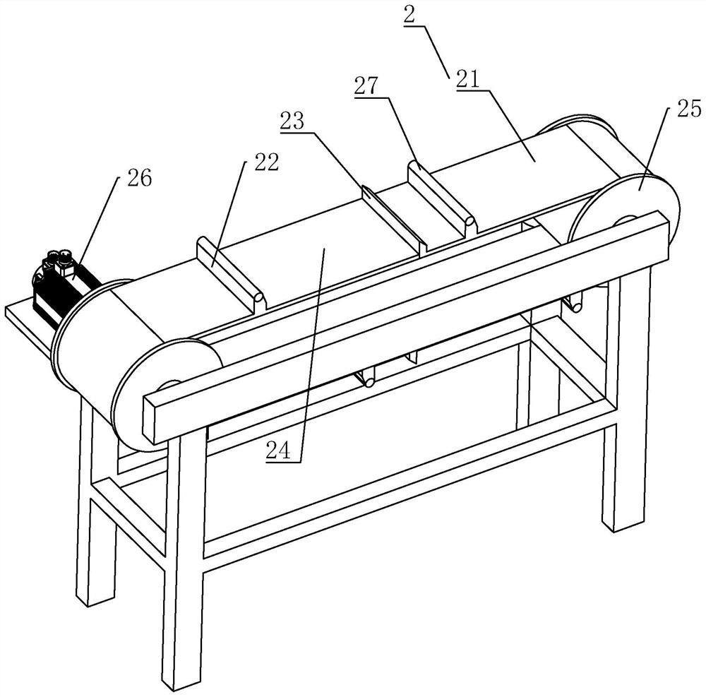
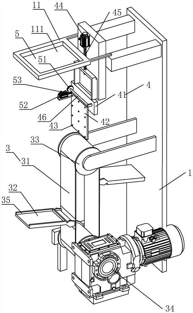
[0030] This embodiment provides a production equipment for the passive film on the surface of photovoltaic cells, the structure is as follows Figure 1-3 As shown in the figure, it includes a body 1, a workbench 11 and a coating unit. One side of the body 1 is from the outside to the workbench 11, and is provided with a horizontal conveying member 2, which is used to accept the battery substrate to the next unit and complete the horizontal transfer of the battery substrate. The vertical lifting member 3 corresponding to the position of receiving the battery substrate on the horizontal conveyor belt 21 and transferring it to the vertical horizontal plane and the transfer member 4 for transferring the battery plate and sending it to the workbench 11 .

[0031] like Figure 1-3 As shown, the horizontal conveying member 2 includes a horizontal conveyor belt 21 rotatably arranged in the horizontal direction. The horizontal conveyor belt 21 is composed of several groups of front baf...


PUM


Abstract

The invention discloses photovoltaic cell surface passivation film production equipment, and relates to the technical field of solar cell production equipment. The equipment comprises a machine body, a workbench and a coating unit, a horizontal conveying part, a vertical lifting part and a transferring part are arranged on one side of the machine body from the outer side to the position of the workbench, and a battery panel can be conveyed to the position adjacent to the vertical lifting part through a horizontal conveying belt and enters an obliquely-arranged bearing plate; according to the solar cell panel feeding and transferring device, automatic feeding and transferring of the solar cell panel can be achieved, the solar cell panel is moved to the bottom of the working table through the horizontal conveying piece, and the solar cell panel is transferred to the top of the vertical lifting piece through the vertical conveying belt and then is transferred through the suction plate on the transferring piece, and the suction plate is rotated to the working table after being lifted. The solar panels are transferred to the suction plate at the bottom of the workbench through the vertical lifting piece, and finally the suction plate rotates to the position of the workbench for film coating, so that automatic feeding of the solar panels can be completed, the production efficiency is greatly improved, and the automatic production process of photovoltaic cells is improved.

Description

technical field [0001] The invention relates to the technical field of solar cell production equipment, in particular to a production equipment for a passive film on the surface of a photovoltaic cell. Background technique [0002] Solar photovoltaic power generation, because of its cleanliness, safety, convenience and high efficiency, has become an emerging industry that is widely concerned and developed around the world. In recent years, the production of crystalline silicon solar cells has developed rapidly, and the technology has continued to improve. At present, most of the crystalline silicon solar cell manufacturers at home and abroad use traditional solar cells, and the technology is relatively mature. [0003] Thin-film solar cells are rechargeable batteries made of thin films through solar energy, and their thickness is as thin as ordinary thin films, generally black or dark. Mainly used in construction, military, travel, national defense, power supply and other ...

Claims


Application Information

Patent Timeline
Patent Type & Authority Applications(China)
IPC IPC(8): H01L21/677H01L21/687H01L31/18
CPCY02P70/50
Inventor 葛伟王云李进章欢欢
Owner 江苏龙恒新能源有限公司
Learn More