Gear cleaning device for building machinery maintenance
A technology for construction machinery and cleaning devices, applied to heating devices, cleaning methods using liquids, dryers, etc., can solve the problems of low cleaning quality and slow cleaning speed, achieve fast cleaning speed, avoid residual water stains, and clean high quality effect
- Summary
- Abstract
- Description
- Claims
- Application Information
AI Technical Summary
Problems solved by technology
Method used
Image
Examples
Embodiment 1
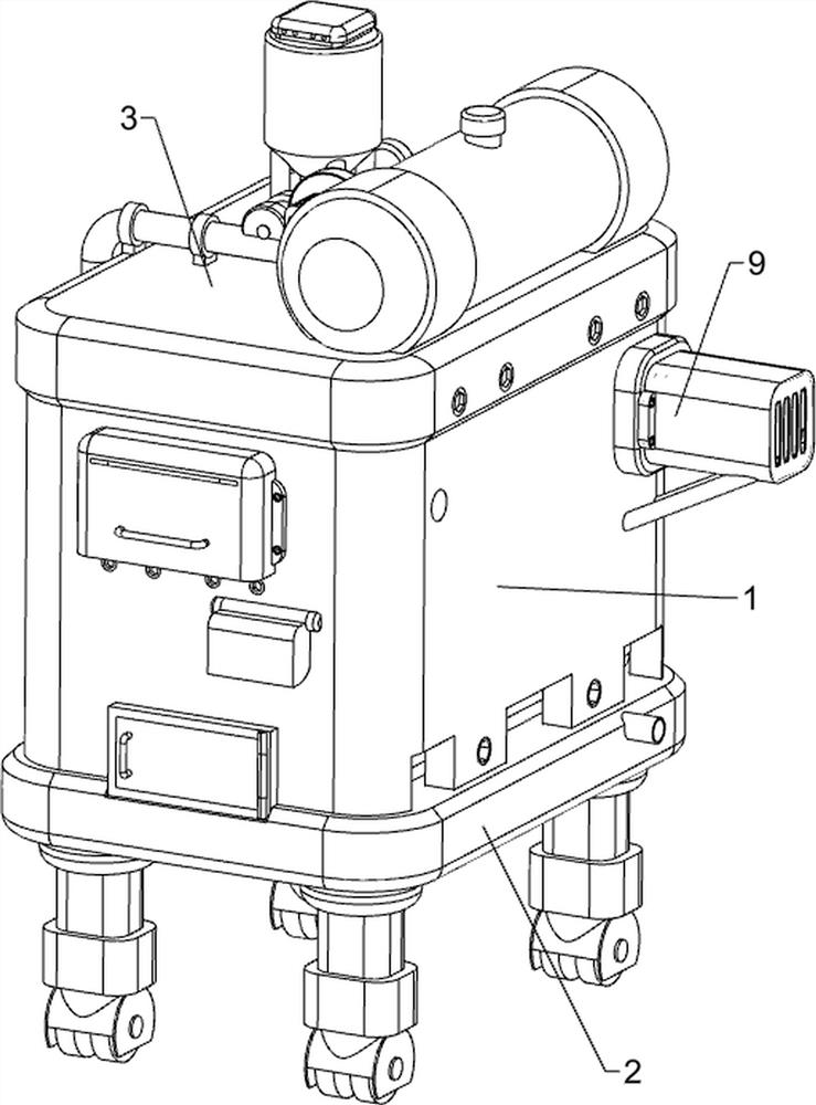
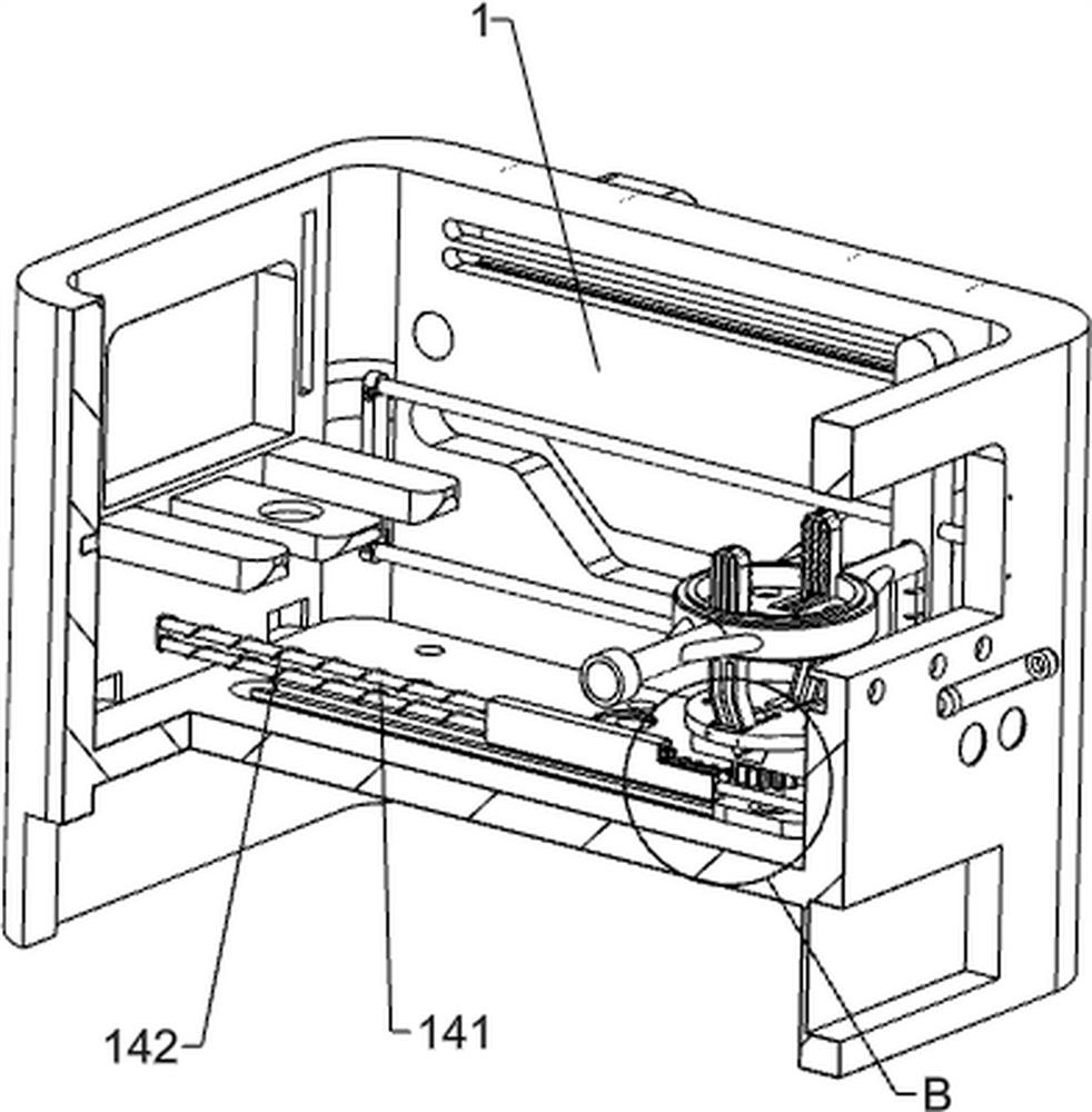
[0041] A gear cleaning device for maintenance of construction machinery, such as Figure 1-Figure 5 As shown, it includes an anti-corrosion bottom box 1, a movable bottom frame 2, a sealed top plate 3, a sealed box 4, a start button 51, a stop button 52, a fixed bottom cover 6, a mounting frame 7, an ultrasonic transducer 71, and a support plate 8 , the driving mechanism 9 and the carrying mechanism 10, the top of the mobile chassis 2 is connected with an anti-corrosion bottom box 1 by welding, and the middle parts of the front and rear sides of the anti-corrosion bottom box 1 are provided with concave curved grooves, and the upper part of the anti-corrosion bottom box 1 passes through The way of bolt connection is connected with a sealed top plate 3, and the left and right sides of the upper part of the anti-corrosion bottom box 1 are provided with a sealed box 4 through bolt removal, and the lower part of the left side of the anti-corrosion bottom box 1 is fixed with a start ...
Embodiment 2
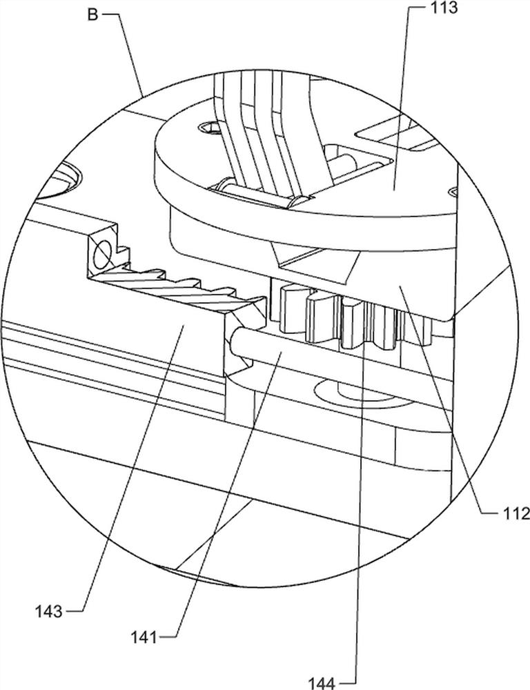
[0046] On the basis of Example 1, such as Figure 6-Figure 8 As shown, a clamping mechanism 11 is also included, and the clamping mechanism 11 includes a movable slider 111, a rotating chassis 112, a positioning bottom plate 113, an auxiliary driving roller 114, a clamping side plate 115, a limit guide rod 116, a second Resetting guide post 117 and second return spring 118, anti-corrosion bottom box 1 is equipped with a movable slider 111 in the middle sliding type, and the middle part of the movable slider 111 is rotatably provided with a rotating chassis 112, and the upper part of the rotating chassis 112 is connected by bolts The positioning base plate 113 is connected in the same way, and the front and rear sides of the middle part of the positioning base plate 113 are rotatably provided with auxiliary rollers 114. The middle part of the positioning base plate 113 is fixedly connected with four limit guide rods 116 at intervals, and the middle part of the rotating circular ...
Embodiment 3
[0051] On the basis of embodiment 1 and embodiment 2, such as Figure 13-Figure 15 As shown, a drying mechanism 13 is also included, and the drying mechanism 13 includes a pressure sensor 131, a shielding frame 132, a force rope 133, a reversing wheel 134, a fixed limit block 135, a third reset guide post 136, a third Return spring 137, heating module 138 and humidity sensor 139, the middle part of right support plate 8 is provided with pressure sensor 131, anti-corrosion bottom box 1 right side is provided with the 3rd reset guide post 136 symmetrically front and back, the 3rd reset guide post 136 upper sliding type is provided with fixed limit block 135, is fixedly connected with shield frame 132 between the fixed limit block 135 of front and rear sides, shield frame 132 top is connected with heating module 138 by the mode of bolt connection, and heating module 138 can To achieve drying of the gears, a third return spring 137 is wound around the third return guide post 136, ...
PUM
 Abstract
Description
Claims
Application Information
 - R&D
- Intellectual Property
- Life Sciences
- Materials
- Tech Scout
- Unparalleled Data Quality
- Higher Quality Content
- 60% Fewer Hallucinations
Browse by: Latest US Patents, China's latest patents, Technical Efficacy Thesaurus, Application Domain, Technology Topic, Popular Technical Reports.
© 2025 PatSnap. All rights reserved.Legal|Privacy policy|Modern Slavery Act Transparency Statement|Sitemap|About US| Contact US: help@patsnap.com


