
Novel apron conveyor slag removal device

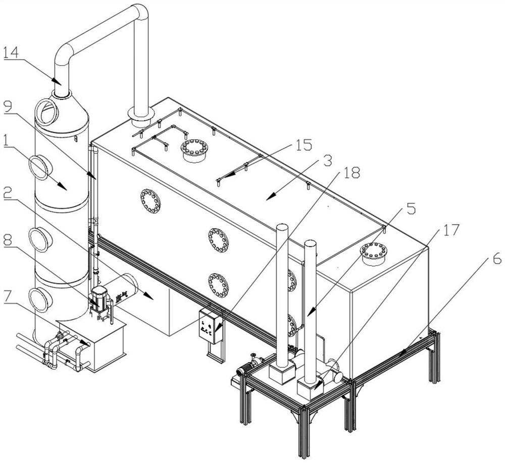
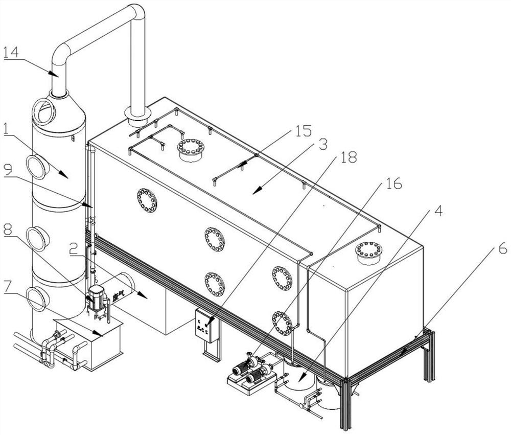
A conveyor and slat technology, applied in the field of garbage disposal equipment, can solve the problems of high noise, waste of energy, and insufficient rhythm, and achieve the effects of reducing noise, reducing power consumption, and optimizing space structure

Pending Publication Date: 2022-04-08
德州众和环保装备制造有限公司
View PDF0 Cites 0 Cited by
  • Summary
  • Abstract
  • Description
  • Claims
  • Application Information

AI Technical Summary

Problems solved by technology

The existing slag removal device of the new scale conveyor is arranged in a straight line, the rhythm is not compact enough, and the requirements for equipment construction space are relatively high
Among them, the scrubber and the exhaust pipe need to lift the air from the bottom up, and the filter box connected to the scrubber and the exhaust pipe needs the air to pass through the equipment horizontally, so that the scrubber and the exhaust pipe need to be equipped with high-power fans or air pumps. waste of energy, noisy

Method used


Image

  • Novel apron conveyor slag removal device
  • Novel apron conveyor slag removal device
  • Novel apron conveyor slag removal device

Examples


Embodiment 1

[0029] Use the following equipment to build deodorization equipment, and compare it with the occupied space of existing deodorization equipment:

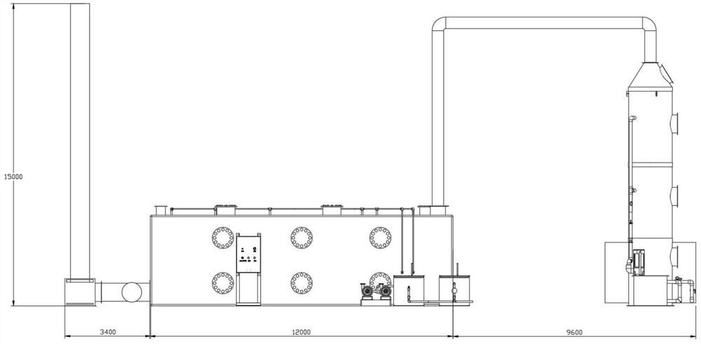
[0030] Filter box specification: 3000 width * 3000 height * 12000 length (mm), washing tower specification: 1500 diameter * 9000 height (mm), silencer box specification: 1000 width, 1000 height, 1000 length (mm).

[0031] Such as image 3 , Figure 4 As shown, in the traditional construction method, the overall length needs to be 25000 mm, while the arrangement method of the present invention occupies only 12800 mm in length, saving more than double the length.

Embodiment 2

[0033] On the basis of Example 1, confirm that the height of the base frame is 3000mm, the processing air volume of the deodorization box is 1500m3 / h, the air pressure is 1500-2500Pa (as PJ-1500 deodorization box), and the exhaust height requirement is 15000mm ("Stink Pollutant Discharge Standard "GB14554-93),

[0034] To meet the above-mentioned air supply standard, the fans to be used at the washing tower are the same, both are TF-151B-3KW fans with a power of 3KW (performance 35000CMH*1500Pa), but since the exhaust pipe is elevated by 3000mm, the exhaust pipe Compared with the existing equipment, the TF-151B2.2KW fan with smaller power can be selected.

[0035] Due to the cover of the filter box, the load on the second liquid pump 16 is increased, but the flow rate of the 40FSB-25 type liquid pump used in the existing deodorization equipment is 500L / h, and the head is 20000mm, which fully meets the liquid supply after transformation. volume requirements.


PUM


Abstract

A novel apron conveyor slag removal device comprises a washing tower, an air pump box, a filter box, a feeding barrel and an exhaust pipe, the air pump box, the washing tower, the filter box and the exhaust pipe are sequentially connected, the feeding barrel is connected with the filter box, the filter box and the exhaust pipe are both carried on a base frame, the air pump box and the feeding barrel are both located in the base frame, and the filter box is connected with the exhaust pipe. The exhaust pipe and the washing tower are located on the same side of the filter box, the filter box comprises a gas inlet box, an alkaline box, a biological box and a gas outlet box, and the gas inlet box, the alkaline box, the biological box and the gas outlet box are sequentially connected from the head end to the tail end. The air power device has the advantages that the positions of the washing tower, the exhaust pipe and the filter box are rearranged, the requirement for an equipment building site is lowered, the air lifting requirement is lowered by raising the filter box, meanwhile, the feeding box and the air pump box are arranged below the filter box, the space structure is further optimized, power consumption of the air power device is lowered, and noise is lowered.

Description

technical field [0001] The invention relates to the field of garbage treatment equipment, in particular to biological deodorization equipment. Background technique [0002] The new scale conveyor slag cleaning device is used to realize the environmental protection treatment before the gas is discharged. The overall equipment is relatively large and needs to occupy a large space. The existing slag cleaning devices of the new scale conveyor are arranged along a straight line, the rhythm is not compact enough, and the requirements for equipment construction space are relatively high. Among them, the scrubber and the exhaust pipe need to lift the air from the bottom up, and the filter box connected to the scrubber and the exhaust pipe needs the air to pass through the equipment horizontally, so that the scrubber and the exhaust pipe need to be equipped with high-power fans or air pumps. Waste of energy, noisy. Contents of the invention [0003] The purpose of the present inv...

Claims


Application Information

Patent Timeline
IPC IPC(8): B01D53/84B01D53/78B01D53/75
CPCY02A50/20
Inventor 张凯强祈冠照马伟伟
Owner 德州众和环保装备制造有限公司
Learn More