Visual bionic photosensitive imaging device and application method

An imaging device, visual bionic technology, applied in the field of visual bionic photosensitive imaging device, can solve the problems of difficult to meet high-precision continuous zoom imaging, not suitable for complex working environment, poor flexibility of focal length adjustment, etc., to improve optical stability and Imaging quality, achieving integration and versatility, and improving the effect of adjustment ability

Active Publication Date: 2022-04-05
NINGBO UNIV
View PDF25 Cites 0 Cited by
  • Summary
  • Abstract
  • Description
  • Claims
  • Application Information

AI Technical Summary

Problems solved by technology

The lens of the device adopts a mechanical focusing method, which has serious mechanical wear and low focusing accuracy; the modified patent optimizes the size of the camera in static state, but the lens size of the device is large when it is in use, which is not suitable for complex working environments; and adopts Planar photosensitive imaging device, there will be problems such as dark corners on the edge of the image, poor imaging effect, etc.
[0005] At present, the traditional optical imaging system mostly adopts mechanical zoom and planar photosensitive imaging, which is faced with problems such as small focusing range, poor edge imaging quality, and poor flexibility of focal length adjustment, making it difficult to meet the needs of high-precision continuous zoom imaging.

Method used


Image

  • Visual bionic photosensitive imaging device and application method
  • Visual bionic photosensitive imaging device and application method
  • Visual bionic photosensitive imaging device and application method

Examples


Embodiment Construction

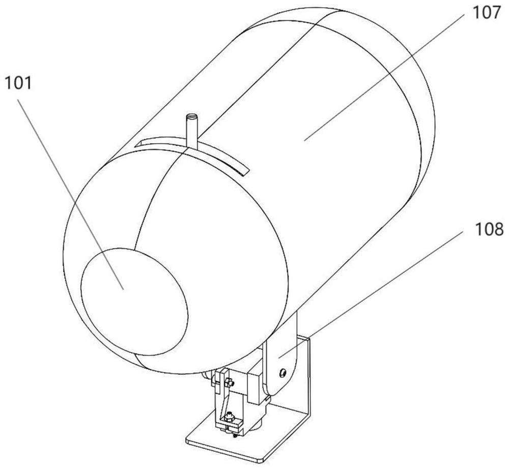
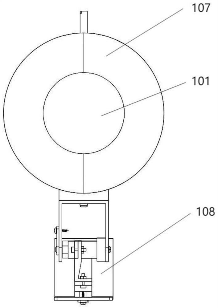
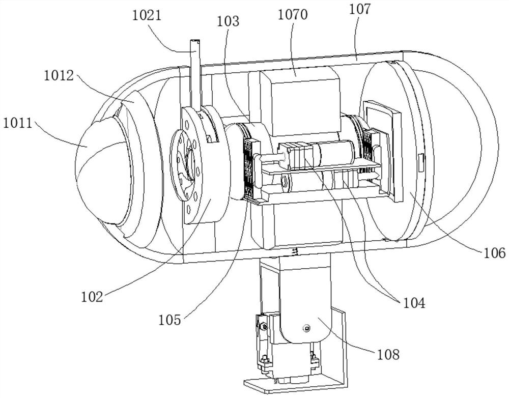
[0033] like Figure 1-Figure 7 As shown, a visual bionic photosensitive imaging device includes a rigid body lens group 101, an aperture stop (102), a bionic adjustable lens module 103, a micro air pump 104, a retractable device 105, a variable image distance bionic image sensing element (106 ), housing 107 and pitch rotation module 108;

[0034] The casing 107 is coaxially arranged with a rigid body lens group 101, an aperture stop 102, a bionic adjustable lens module 103, and a variable image distance bionic image sensing element 106; a micro air pump 104 and a retractable device 105 are installed in the casing Inside the body 107, the variable image distance bionic image sensing element 106 can slide axially relative to the housing 107;

[0035] The bionic tunable lens module 103 includes a first tunable lens 1031, a second tunable lens 1032 and a porous glass inner lens 1033; the first tunable lens 1031 includes an optical elastic film 10311, a lens housing 10312 and an o...


PUM


Abstract

The invention discloses a visual bionic photosensitive imaging device and an application method. The visual bionic photosensitive imaging device comprises a rigid body lens group, an aperture diaphragm, a bionic adjustable lens module, a micro air pump, a telescopic device, a variable image distance bionic image sensing element, a shell and a pitching rotation module, a rigid body lens group, an aperture diaphragm, a bionic adjustable lens module and a variable image distance bionic image sensing element are coaxially arranged in the shell in sequence; the miniature air pump and the telescopic device are installed in the shell, and the variable image distance bionic image sensing element can slide in the axial direction relative to the shell. The bionic adjustable lens module comprises a first adjustable lens, a second adjustable lens and a porous glass inner lens; the first adjustable lens and the second adjustable lens are respectively in threaded connection with the porous glass inner lens and are sealed by inner sealing rings; the pitching rotating module is installed at the bottom of the shell so as to drive the shell to do pitching and rotating motion. The device has the advantages of being compact in structure, large in observation range and capable of achieving curved surface light sensing and double-shaft rotation.

Description

technical field [0001] The invention relates to a bionic visual imaging device, in particular to a visual bionic photosensitive imaging device and an application method. Background technique [0002] With the development and progress of technology, people have higher and higher requirements for the integration, portability and focusing ability of visual imaging equipment. The optical lens and its variable magnification imaging module are the key parts of the visual imaging equipment, which have an important impact on the structural composition, adjustment characteristics and imaging quality of the visual imaging system. [0003] The Chinese patent with the publication number CN204329962U discloses a high-precision novel bionic eye device, which is composed of a rotating and pitching head, a bidirectional ball screw slide, two tricept bionic eyes and a computer. The rotating and tilting head can realize the rotation and pitching motion of the bionic eye around the axis of th...

Claims


Application Information

Patent Timeline
Patent Type & Authority Applications(China)
IPC IPC(8): G02B3/14G02B3/00G02B7/02G02B7/04G02B13/00G03B17/12H04N5/225H04N5/335
Inventor 梁丹罗钦泽崔玉国余丰卜佳健翟占虎
Owner NINGBO UNIV
Why Eureka
Try Eureka