A Bionic Flexible Mobile Optical Imaging Device

An optical imaging, bionic flexible technology, applied in optics, optical components, installation, etc., can solve the problem that the adaptability and flexibility of the overall device is not high enough, multi-directional, multi-angle observation, optical axis stability, response The speed is not high enough to achieve the effect of improving optical stability and imaging quality, multi-optical design freedom, and improving visual range and controllability

Active Publication Date: 2021-11-23
宁波奇镜科技有限公司
View PDF6 Cites 0 Cited by
  • Summary
  • Abstract
  • Description
  • Claims
  • Application Information

AI Technical Summary

Problems solved by technology

Most of the tunable lenses in the prior art have problems such as small observation range, insufficient adaptability and flexibility. Taking the electrowetting tunable lens as an example, although continuous and large-magnification optical adjustment can be realized during the adjustment process, the optical The stability and response speed of the axis are not high enough; while the traditional glass lens group can adjust the focal length by adjusting the distance between the lens groups, and the imaging quality is high, but the adjustment mechanism is complicated and the overall size of the device is difficult to meet the needs of integration
In addition, the existing adjustable lenses are basically fixed. Although the stability of imaging is guaranteed, the observation range of the imaging device is limited, and multi-directional and multi-angle observation cannot be achieved, which makes the overall device adaptability and The flexibility is not high enough, and there are certain limitations in the use process

Method used


Image

  • A Bionic Flexible Mobile Optical Imaging Device
  • A Bionic Flexible Mobile Optical Imaging Device
  • A Bionic Flexible Mobile Optical Imaging Device

Examples


Embodiment Construction

[0033] The following will clearly and completely describe the technical solutions in the embodiments of the present invention with reference to the accompanying drawings in the embodiments of the present invention. Obviously, the embodiments described below are some, not all, embodiments of the present invention. Based on the embodiments of the present invention, all other embodiments obtained by persons of ordinary skill in the art without making creative efforts belong to the protection scope of the present invention.

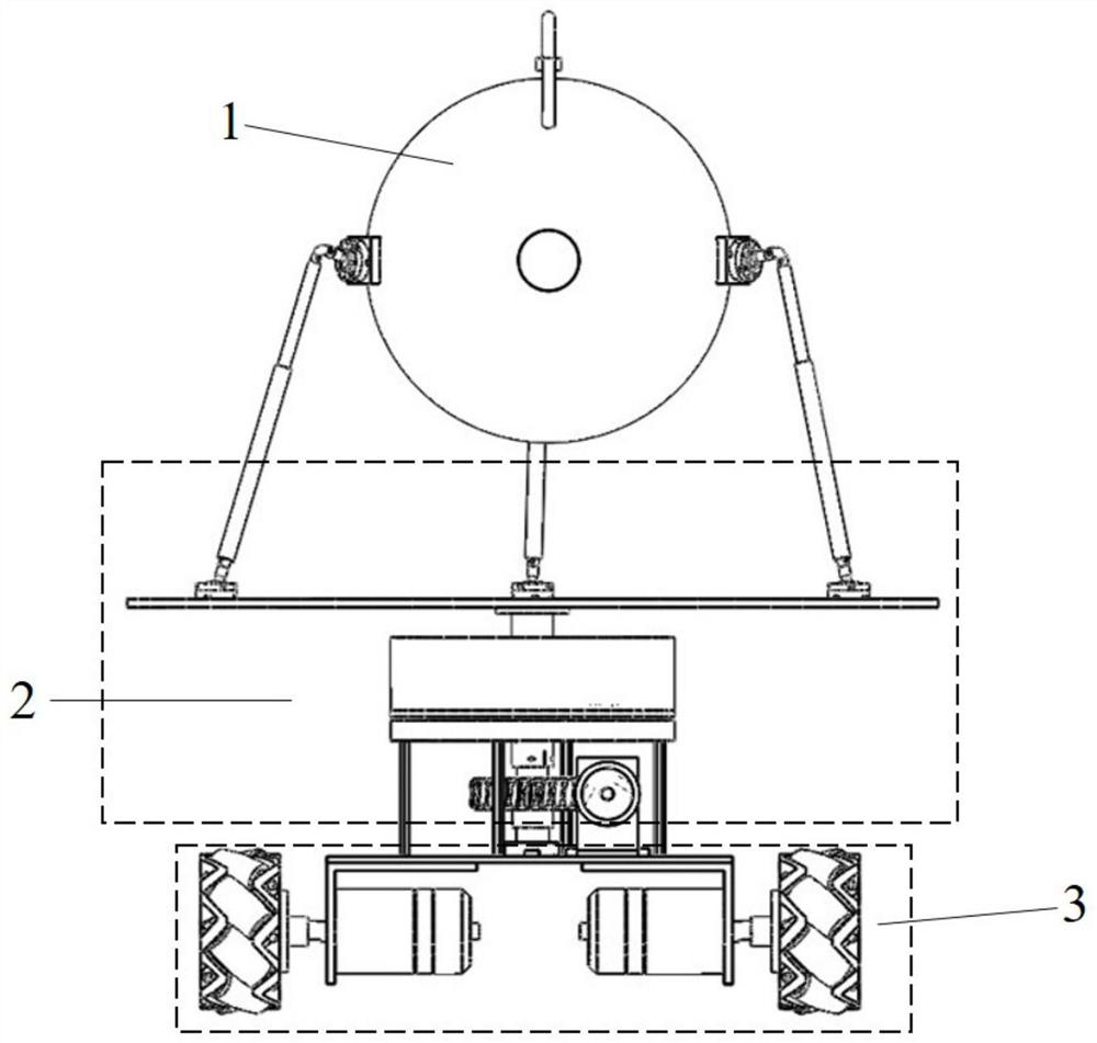
[0034] Such as figure 1 As shown, a bionic flexible mobile optical imaging device provided by the present invention includes a bionic flexible optical device 1 , a rotating mechanism 2 and a mobile chassis 3 .

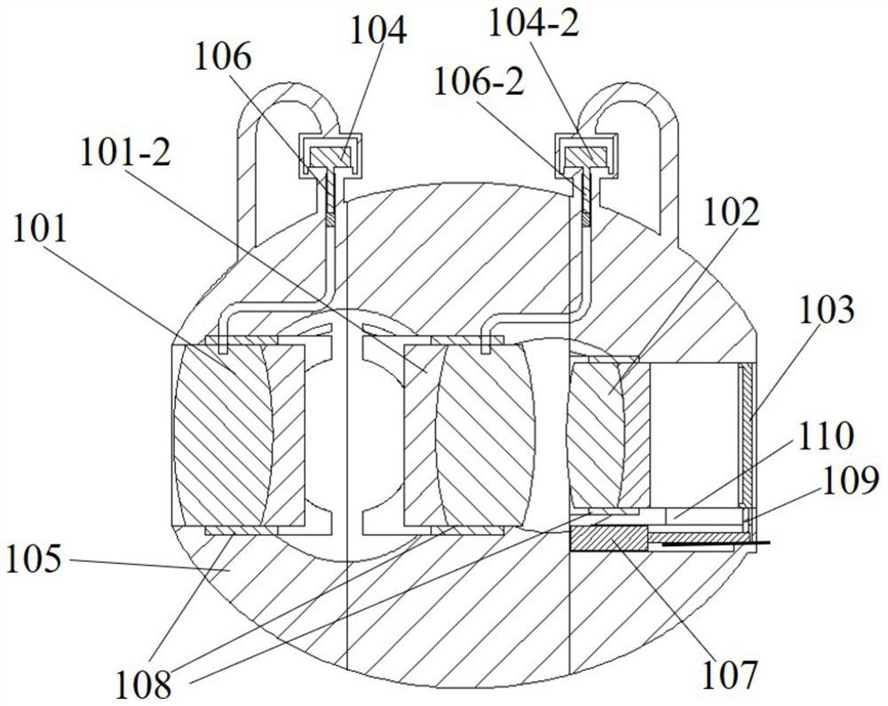
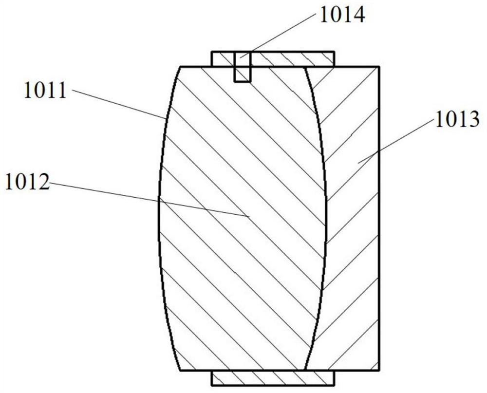
[0035] Such as figure 2 , image 3 , Figure 8 As shown, the bionic flexible optical device 1 includes a first flexible lens 101, a second flexible lens 101-2, a double-glued glass lens 102, a CCD module 103, an ultrasonic linear motor 104, a ball m...


PUM


Abstract

The invention discloses a bionic flexible mobile optical imaging device, which comprises a bionic flexible optical device, a rotating mechanism and a mobile chassis. The bionic flexible optical device uses flexible lenses, optical liquids, and glass lenses as the main refractive medium. During the imaging process, the ultrasonic linear motor squeezes the liquid through the piston to deform the outer surface of the flexible lens, thereby changing the focal length of the flexible lens and synergistically adjusting The focal length of the two flexible lenses can realize continuous focus adjustment of the device. The rotating mechanism and mobile chassis have camera attitude control and motion control functions, which can realize multi-directional and multi-angle observation of the entire device. The invention has the characteristics of compact structure, stable optical axis, large observation range and dual-axis rotation and movement, and can be applied to various modern optical imaging devices.

Description

technical field [0001] The invention relates to a bionic visual imaging device, in particular to a bionic flexible mobile optical imaging device. Background technique [0002] With the development and progress of technology, people have higher and higher requirements for the integration, portability and focusing ability of visual imaging equipment. In recent years, new tunable lenses have attracted extensive attention from researchers at home and abroad. Most of the tunable lenses in the prior art have problems such as small observation range, insufficient adaptability and flexibility. Taking the electrowetting tunable lens as an example, although continuous and large-magnification optical adjustment can be realized during the adjustment process, the optical The stability and response speed of the axis are not high enough; while the traditional glass lens group can adjust the focal length by adjusting the distance between the lens groups, and the imaging quality is high, bu...

Claims


Application Information

Patent Timeline
Patent Type & Authority Patents(China)
IPC IPC(8): G02B26/00G02B3/14G02B7/04
CPCG02B26/004G02B3/14G02B7/04
Inventor 梁丹鲁晟燚周宇梁冬泰
Owner 宁波奇镜科技有限公司
Why Eureka
Try Eureka