
Clamp, glue dispensing clamp assembly and glue removing clamp assembly

A jig and glue dispensing technology, which is applied to devices and coatings that apply liquid to the surface. glue effect

Active Publication Date: 2022-04-05
DONGGUAN HUABEL ELECTRONICS TECH
View PDF8 Cites 0 Cited by
  • Summary
  • Abstract
  • Description
  • Claims
  • Application Information

AI Technical Summary

Problems solved by technology

However, the existing dispensing jig cannot be rotated and cannot cover the upper case and the lower case together, resulting in the need for human hands to cover the upper case and the lower case together, which has the problem of low production efficiency
In addition, after the dispensing machine dispenses glue on the upper and lower casings on the dispensing jig, it is necessary to disassemble the formed earphone housing from the dispensing jig, and then position the earphone housing on the dispensing jig. On the glue removal jig for glue removal, due to the need to take and place the earphone shell many times, it is easy to cause scratches on the earphone shell, and there are problems of damaging the glue dispensing path and wasting man-hours

Method used


Image

  • Clamp, glue dispensing clamp assembly and glue removing clamp assembly
  • Clamp, glue dispensing clamp assembly and glue removing clamp assembly
  • Clamp, glue dispensing clamp assembly and glue removing clamp assembly

Examples


Embodiment Construction

[0027] In order to describe the technical content and structural features of the present invention in detail, further description will be given below in conjunction with the implementation and accompanying drawings.

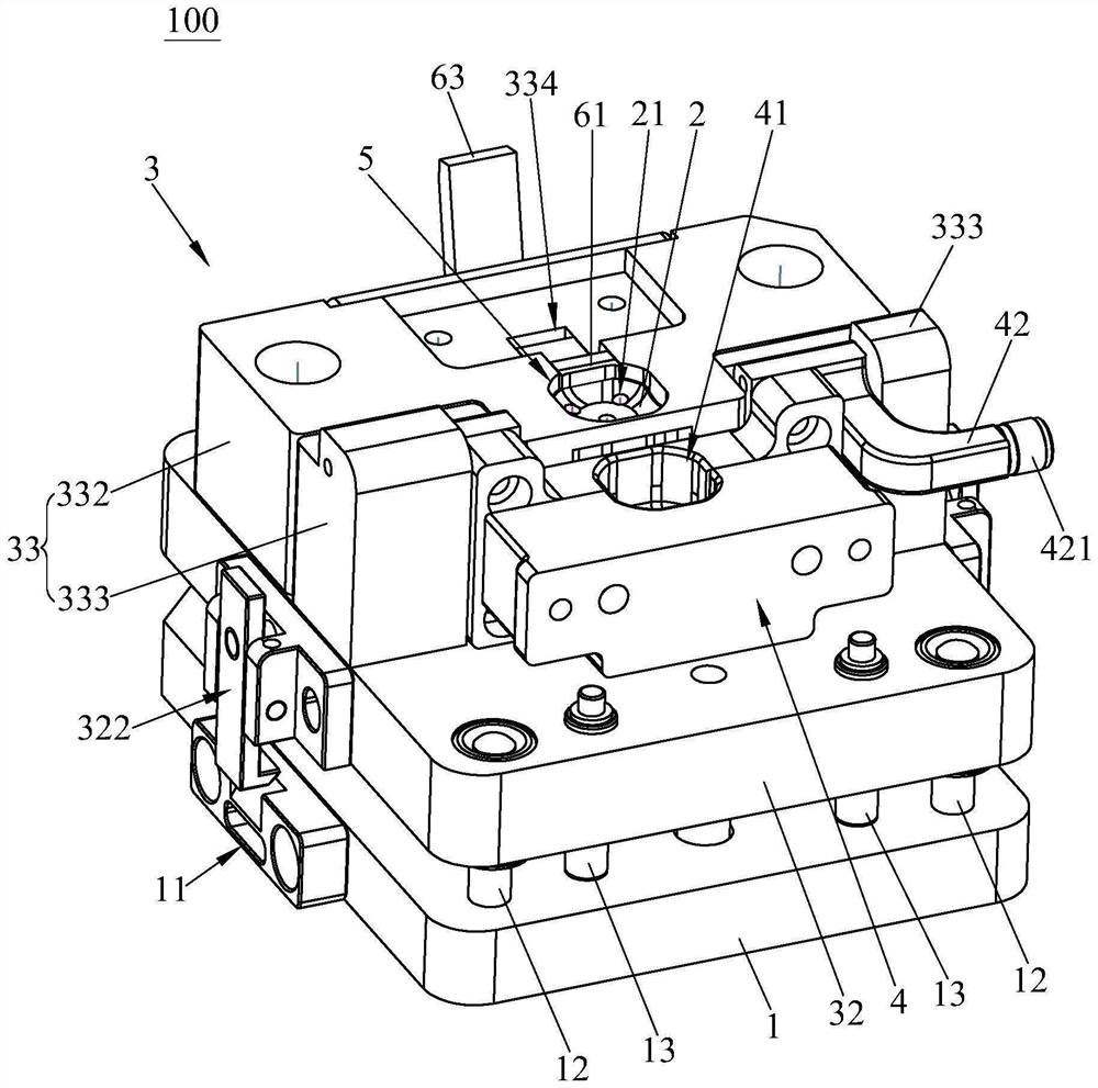
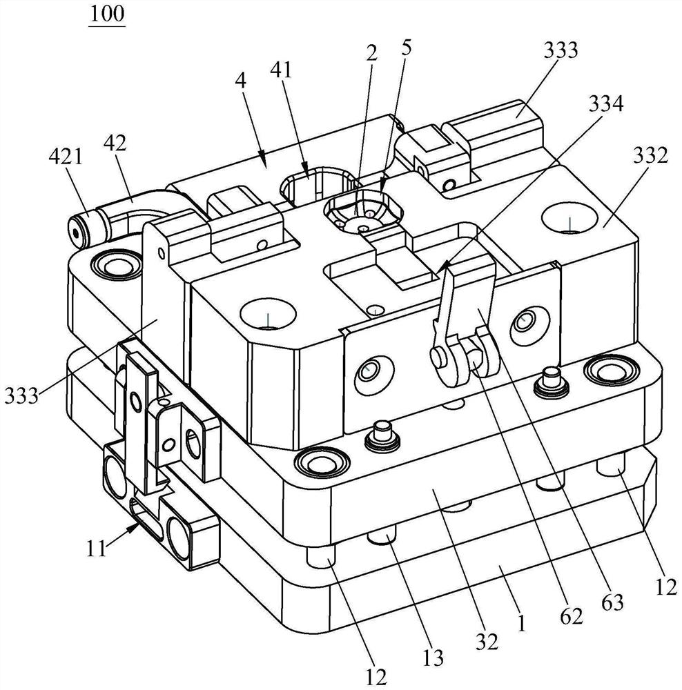
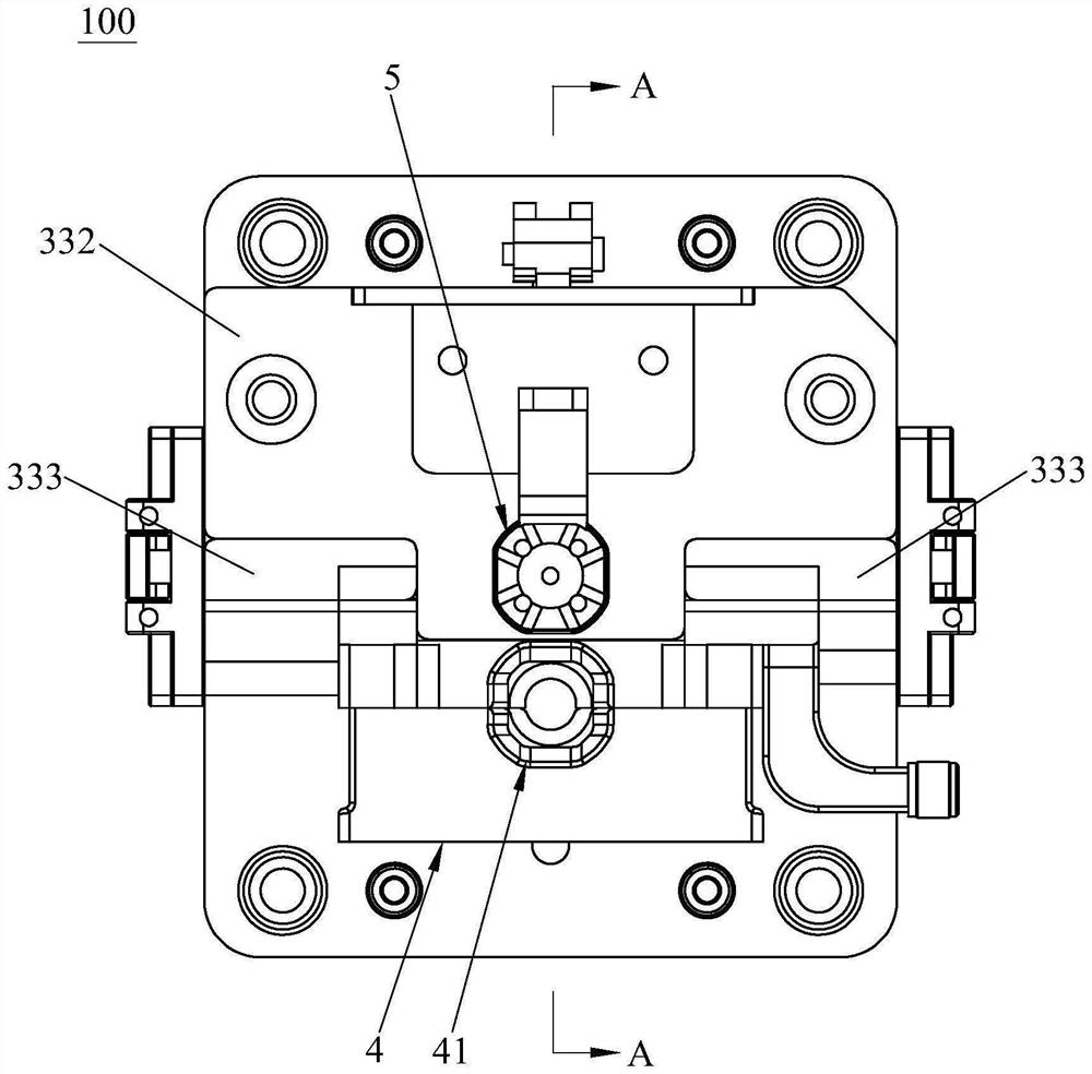
[0028] see Figure 1 to Figure 4 , the fixture 100 of the present invention includes a fixture base 1, a fixed module 2, a lifting module 3 and a rotating module 4, the fixed module 2 is fixed on the fixture base 1, and the lifting module 3 is arranged on the fixture base 1 in a liftable manner , and the lifting module 3 is provided with a through hole 31, the lifting module 3 is sleeved on the fixed module 2 through the through hole 31, and the upper end of the fixed module 2 and the inner wall of the through hole 31 are provided with a hole for positioning the first workpiece The first accommodating chamber 5; specifically, the upper end of the fixed module 2 has a bearing concave surface for bearing workpieces. The rotating module 4 is rotatably connected to ...


PUM


Abstract

The invention provides a clamp, a dispensing clamp assembly and a glue cleaning clamp assembly.The clamp comprises a clamp base, a fixing module, a lifting module and a rotating module, the fixing module is fixed to the clamp base, the lifting module is arranged on the clamp base in a lifting mode, a through hole is formed in the lifting module, the fixing module is sleeved with the lifting module through the through hole, and the rotating module is arranged on the lifting module; a first containing cavity is defined by the upper end of the fixed module and the inner wall of the through hole, the rotating module is rotationally connected to the lifting module, and a second containing cavity is formed in the rotating module. The fixture can be matched with the dispensing machine, and the rotating module of the fixture is driven by the dispensing machine to rotate, so that the second workpiece positioned in the second accommodating cavity and the first workpiece positioned in the first accommodating cavity are covered together, and circumferential dispensing can be performed on a product formed by the first workpiece and the second workpiece in multiple directions; the lifting module of the clamp has the function of driving the product to be automatically demoulded, so that the product can be completely exposed out of the glue cleaning surface, and glue cleaning is facilitated.

Description

technical field [0001] The invention relates to the field of glue dispensing technology, in particular to a fixture, a glue dispensing fixture assembly and a glue clearing fixture assembly. Background technique [0002] Headphones are conversion units that receive electrical signals from media players or receivers and convert them into audible sound waves using speakers close to the ears. The shell of the earphone usually includes an upper shell and a lower shell. When assembling the shell, it is usually necessary to cover the upper shell and the lower shell together, and then circle the connection between the upper shell and the lower shell. Dispensing. However, the existing glue dispensing jig cannot be rotated and cannot cover the upper case and the lower case together, resulting in the need for human hands to cover the upper case and the lower case together, which has the problem of low production efficiency. In addition, after the dispensing machine dispenses glue on ...

Claims


Application Information

Patent Timeline
Patent Type & Authority Applications(China)
IPC IPC(8): B05C5/02B05C13/02B05C9/12
CPCY02P70/50
Inventor 刘玉金雷中华杜寿雷董火欢苏凯豪刘晓强
Owner DONGGUAN HUABEL ELECTRONICS TECH
Learn More