
Carbon fiber ridge horn antenna unit and manufacturing method thereof

An antenna unit and carbon fiber technology, applied in the microwave field, can solve problems such as complex molding process, achieve good sealing effect, significant light weight, and reduce loss

Active Publication Date: 2022-04-01
CHINA ELECTRONICS TECH GRP CORP NO 14 RES INST
View PDF10 Cites 0 Cited by
  • Summary
  • Abstract
  • Description
  • Claims
  • Application Information

AI Technical Summary

Problems solved by technology

[0003] At present, domestic carbon fibers are mainly used in simple components such as Yagi antennas and S horn antennas in the field of radar antennas in China. However, there are no relevant literature reports on complex components such as carbon fiber ridge horns due to their complicated molding process.

Method used


Image

  • Carbon fiber ridge horn antenna unit and manufacturing method thereof
  • Carbon fiber ridge horn antenna unit and manufacturing method thereof
  • Carbon fiber ridge horn antenna unit and manufacturing method thereof

Examples


Embodiment 1

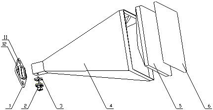
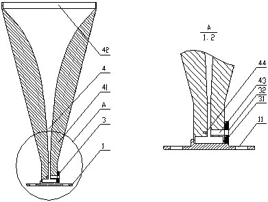
[0027] Such as figure 1 As shown, the outdoor waterproof carbon fiber ridge horn antenna unit of the present invention includes a carbon fiber base 1, a bayonet type double-sealed SMA connector 2, an aluminum alloy mounting flange 3, a carbon fiber ridge horn 4, polyethersulfone foam 5, and glass cloth 6.

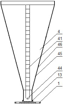
[0028]The carbon fiber ridge speaker 4 and the carbon fiber base 13 are bonded firmly with epoxy resin, and the carbon fiber ridge speaker 4 and the aluminum alloy flange 31 are bonded with epoxy resin to ensure structural strength, and Spread conductive glue around to ensure good electrical continuity between the outer surface of the carbon fiber ridge horn 4 and the aluminum alloy flange 3; Molding, the inner surface 45 is selected as the bonding surface of the mold core 8. Since the thickness of the ridge is obviously greater than the thickness of the outer wall 46 of the horn, in order to avoid defects such as bridging, discounting, and air trapping when laying layers w...

Embodiment 2

[0032] A method for manufacturing a carbon fiber ridge horn antenna unit. The carbon fiber ridge horn antenna unit manufactured by the method includes: a carbon fiber base 1, a bayonet type double-sealed SMA connector 2, an aluminum alloy mounting flange 3, a carbon fiber ridge horn 4, and polyethersulfone Foam 5, glass cloth 6; the main body of the antenna unit includes a carbon fiber ridge horn, a carbon fiber base and an aluminum alloy flange; the method includes the following steps:

[0033] Step 1. The carbon fiber ridge speaker 4 and the carbon fiber base 13 are bonded firmly with epoxy resin, and the carbon fiber ridge speaker 4 and the aluminum alloy flange 31 are bonded with epoxy resin to ensure the structure strength, and apply conductive glue around to ensure good electrical continuity between the outer surface of the carbon fiber ridge horn 4 and the aluminum alloy flange 3; The male mold is used for molding, and the inner surface 45 is selected as the bonding sur...


PUM


Abstract

The invention provides an outdoor waterproof carbon fiber ridge horn antenna unit and a manufacturing method thereof. The outdoor waterproof carbon fiber ridge horn antenna unit has good process realizability on the basis of ensuring the electrical performance of the antenna unit. Reliable sealing between the connector and an antenna unit and between the connector and a cable interconnection part can be effectively ensured by adopting the bayonet type double-sealing SMA connector; the waterproof requirement of the horn mouth can be effectively met through polyethersulfone foam and multi-layer glass cloth encapsulation.

Description

technical field [0001] The invention belongs to the field of microwave technology, and in particular relates to a carbon fiber ridge horn antenna unit and a manufacturing method thereof. Background technique [0002] The horn antenna with ridges can effectively expand the working bandwidth of the antenna unit due to the capacitive effect between the ridges, and is widely used as a broadband antenna unit, which is very important in the field of antenna technology. With the increasingly higher requirements for the mobility, high reliability and long life design of radar, the traditional metal antenna unit structure design optimization has no more room for weight reduction, and carbon fiber composite materials with higher specific strength are gradually being used In the design of radar antenna unit with simple structure, such as Yagi antenna, S horn antenna (manufacturing method of carbon fiber composite material S horn CN 104441685 A), etc. For a lightweight front, the use o...

Claims


Application Information

Patent Timeline
Patent Type & Authority Applications(China)
IPC IPC(8): H01Q13/02H01Q1/50
CPCY02D30/70
Inventor 刘继兴操卫忠逯建伟华海涛
Owner CHINA ELECTRONICS TECH GRP CORP NO 14 RES INST
Learn More