
Self-circulation self-rotation row conveying belt cleaning machine

A conveyor belt and cleaning machine technology, applied in the field of cleaning machines, can solve problems such as inability to circulate waste water, clean the conveyor belt, and large wear of the conveyor belt, and achieve the effects of preventing muddy water splashing, efficient cleaning, and good environmental performance

Pending Publication Date: 2022-04-01
中煤(天津)地下工程智能研究院有限公司 +2
View PDF0 Cites 0 Cited by
  • Summary
  • Abstract
  • Description
  • Claims
  • Application Information

AI Technical Summary

Problems solved by technology

[0003] 1. The existing similar cleaning device wears a lot on the conveyor belt, and does not clean the upper surface of the conveyor belt. The principle is to wet the material remaining on the conveyor belt, increase its moisture, and reduce the adhesion between the material and the conveyor belt. Focus on using the follow-up cleaning mechanism to remove the material and water. This method has a certain effect on conventional materials and general low-to-medium speed roller belt conveyors, but it has a certain effect on viscous materials and air-suspension belt conveyors. Machines and roller belt conveyors with high belt speeds are not effective
[0004] 2. The existing similar cleaning devices cannot recycle the waste water generated, and the waste cleaning cannot be solved, which will seriously affect the efficiency of the entire cleaning device and cannot meet the economic and environmental requirements

Method used


Image

  • Self-circulation self-rotation row conveying belt cleaning machine
  • Self-circulation self-rotation row conveying belt cleaning machine
  • Self-circulation self-rotation row conveying belt cleaning machine

Examples


Embodiment Construction

[0028] In order to make the technical means, creative features, goals and effects achieved by the present invention easy to understand, the present invention will be further elaborated below in conjunction with specific embodiments, but the following embodiments are only preferred embodiments of the present invention, not all. Based on the examples in the implementation manners, other examples obtained by those skilled in the art without making creative efforts all belong to the protection scope of the present invention. The experimental methods in the following examples, unless otherwise specified, are conventional methods, and the materials, reagents, etc. used in the following examples, unless otherwise specified, can be obtained from commercial sources.

[0029] Example:

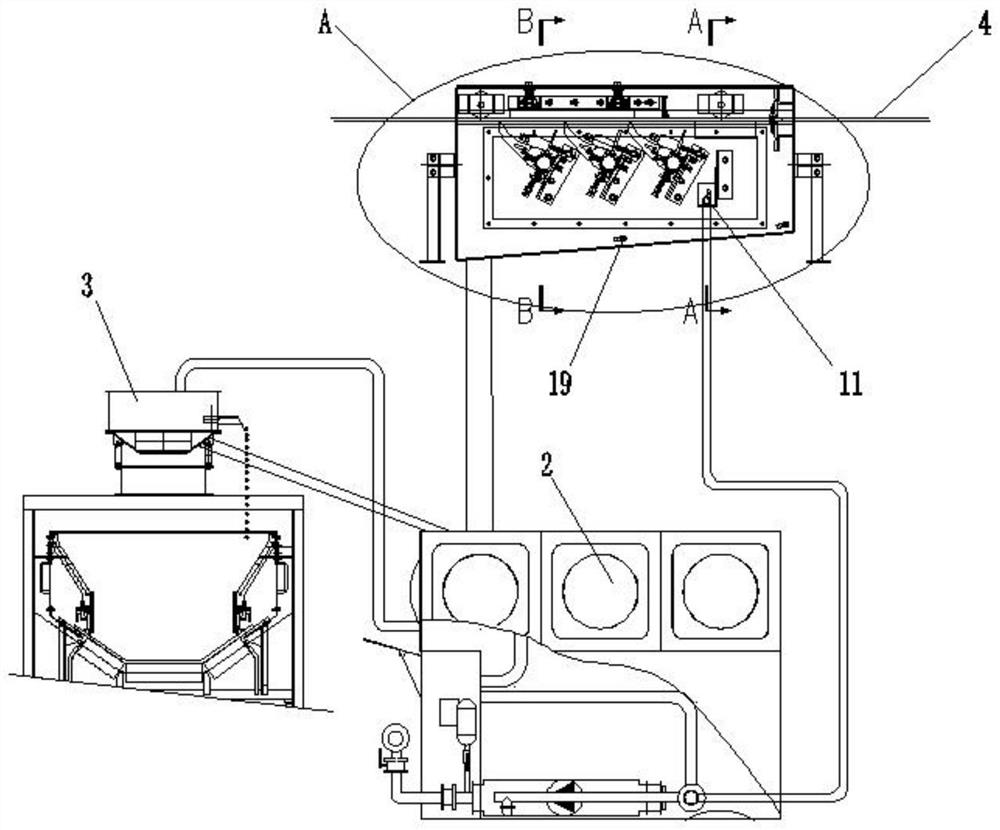
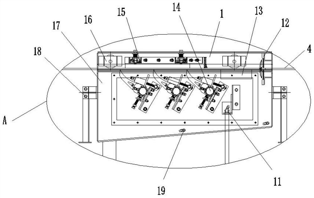
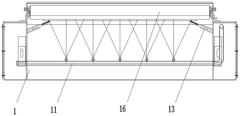
[0030] Such as Figure 1-Figure 4 As shown, a self-circulating self-rotation row conveyor belt cleaning machine includes a cleaning device 1, a circulating water treatment device 2 and a dehydration dev...


PUM


Abstract

The invention discloses a self-circulation autorotation row conveying belt cleaning machine which comprises a cleaning device, a circulating water treatment device and a dewatering device, and a conveying belt body is arranged in the cleaning device; the cleaning device is located in the box body mechanism, a supporting mechanism is installed on the outer wall of the box body mechanism in the running direction of the conveying belt body, and a box body washing mechanism is installed on a bottom plate of the box body mechanism. The cleaning device comprises a washing mechanism arranged on the inner side wall of the box body mechanism, and a sealing mechanism is arranged at the position, entering the box body mechanism, of the conveying belt body. A water retaining mechanism is arranged over the washing mechanism, a water removing mechanism is arranged on the left side of the washing mechanism, and an upper cleaning and water removing mechanism is arranged above the conveying belt body. By arranging the cleaning device, the outer surface of the conveying belt can be cleaned conveniently and cannot be damaged, meanwhile, the circulating water treatment device and the dewatering device can treat waste water, and therefore water can be recycled conveniently, and the purpose of environmental protection is achieved.

Description

technical field [0001] The invention relates to the technical field of cleaning machines, in particular to a self-circulating and self-rotating conveyor belt cleaning machine. Background technique [0002] Belt conveyors are used for medium and short-distance bulk material transportation in coal, mining, electric power and other industries. Generally, belt conveyors are equipped with cleaning devices at the unloading return section of the machine head. The cleaning device at the existing head roller can clean large It is difficult to completely clean the coal dust on the surface of the belt conveyor belt, and there will always be some coal dust on the upper and lower surfaces of the conveyor belt, which will lead to the formation of dust during the subsequent operation of the belt conveyor. As a result, the number of dust particles in the environment increases sharply, and the dust and mist are lingering, which fails to meet the environmental protection requirements, and aff...

Claims


Application Information

Patent Timeline
Patent Type & Authority Applications(China)
IPC IPC(8): B65G45/22
Inventor 郭庆华张福录王涛王玉亮张宝宝王利欣练存才李章成刘二朋张文杰张凯邓伟张源野
Owner 中煤(天津)地下工程智能研究院有限公司
Learn More