Output circuit and electronic device

An output circuit and amplifying circuit technology, applied in the layout of amplifier protection circuits, electronic switches, components of amplifier devices, etc., can solve the problems of small output current, large volume and high cost

Pending Publication Date: 2022-03-29
PEITIAN ROBOTICS CO LTD
View PDF0 Cites 0 Cited by
  • Summary
  • Abstract
  • Description
  • Claims
  • Application Information

AI Technical Summary

Problems solved by technology

[0002] In industrial products, there are many kinds of input level requirements, which need to be adapted by changing the external resistance, and the general output end will have different driving capabilities and withstand voltage requirements due to the size of the load. In the traditional optocoupler output circuit The output current is very small, even if an ordinary Darlington tube (Darlington tube) is integrated, the output current is very small, and the output circuit is easily damaged by overcurrent. The tube (MOS, Metal-Oxide-Semicon ductor Field-Effect Transistor) is inside, which is large in size and high in cost, and the triode cannot withstand excessive reverse voltage. When the polarity of the output signal is reversed, power-on will damage the output

Method used


Image

  • Output circuit and electronic device
  • Output circuit and electronic device
  • Output circuit and electronic device

Examples


Embodiment Construction

[0012] The following will clearly and completely describe the technical solutions in the embodiments of the present application with reference to the drawings in the embodiments of the present application. Obviously, the described embodiments are only some of the embodiments of the present application, not all of them. Based on the embodiments in this application, all other embodiments obtained by persons of ordinary skill in the art without making creative efforts belong to the scope of protection of this application.

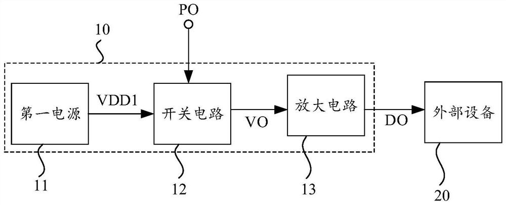
[0013] see figure 1 , figure 1 It is a schematic structural diagram of an embodiment of an output circuit provided in the present application. The output circuit 10 includes: a first power supply 11 , a switch circuit 12 and an amplifier circuit 13 .

[0014] The first power supply 11 is connected to the switch circuit 12 for outputting a first power supply signal VDD1 to the switch circuit 12, and the first power supply signal VDD1 may be a DC signal.

[00...


PUM


Abstract

The invention discloses an output circuit. The output circuit comprises a first power supply, a switching circuit and an amplifying circuit, the first power supply outputs a first power supply signal; the switching circuit is connected with the first power supply and is used for receiving the control signal and the first power supply signal, and when the voltage value of the control signal falls within a preset voltage range, the switching circuit is switched on and outputs a voltage signal; and the amplifying circuit is connected with the switching circuit and is used for amplifying the voltage signal and outputting an amplified signal to external equipment when the switching circuit is switched on. In this way, the amplified current can be safely and stably output.

Description

technical field [0001] The present application relates to the technical field of integrated circuits, in particular to an output circuit and an electronic device. Background technique [0002] In industrial products, there are many kinds of input level requirements, which need to be adapted by changing the external resistance, and the general output end will have different driving capabilities and withstand voltage requirements due to the size of the load. In the traditional optocoupler output circuit The output current is very small, even if an ordinary Darlington tube (Darlington tube) is integrated, the output current is very small, and the output circuit is easily damaged by overcurrent. The tube (MOS, Metal-Oxide-Semicon ductor Field-Effect Transistor) is inside, which is large in size and high in cost, and the triode cannot withstand excessive reverse voltage. When the polarity of the output signal is reversed, power-on will damage the output. Contents of the invent...

Claims


Application Information

Patent Timeline
Patent Type & Authority Applications(China)
IPC IPC(8): H03K17/30H03F1/52G05F1/46G05F1/569
CPCH03K17/30H03K17/302H03F1/52H03F1/523G05F1/461G05F1/569
Inventor 唐明军
Owner PEITIAN ROBOTICS CO LTD
Why Eureka
Try Eureka