


Quick Research
Generate reliable direction feasibility study reports for your R&D in just a few steps.

Technical Q&A
Discover and master advanced knowledge NOW. Basics, ideas, possibilities, all at once.

Find Solutions
As an expert in R&D theories, this can generate solutions to your technical problems instantly.

Evaluate Feasibility
Analyze your overall solution with one click, know your potential R&D risks in advance.

Monitor Landscape
Get weekly tech updates, stay abreast of the latest tech innovations and key insights.
Intelligent regulating valve throttling and pressure reducing device and intelligent regulating valve
A technology of intelligent adjustment and decompression device, which is applied in the direction of valve device, wellbore/well valve device, valve operation/release device, etc. Closure, valve core is easy to be eroded and damaged, etc., to achieve the effect of no maintenance of the structure, stable driving process and good sealing performance
- Summary
- Abstract
- Description
- Claims
- Application Information
AI Technical Summary
Problems solved by technology
Method used
Image

Examples
Embodiment 1
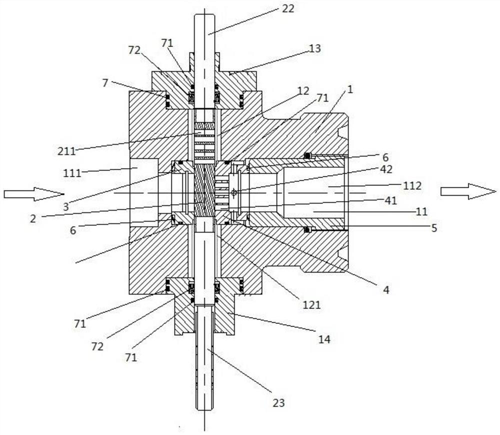
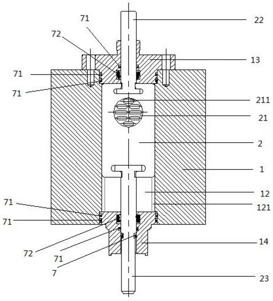
[0049] Such as Figure 1-2 As shown, an intelligent regulating valve throttling and decompression device includes a valve body 1 with a cross-shaped hole, the left and right ends of the horizontal hole 11 are respectively connected to fluid pipelines, and the vertical hole 12 includes a rectangular slideway 121; It includes a valve core 2, an upper valve stem 22 and a lower valve stem 23 arranged on the rectangular slideway 121. The valve core 2 is a cuboid slide plate type, and a number of horizontal throttling valves are provided corresponding to the position of the horizontal hole 11. hole 211; the upper valve rod 22 and the lower valve rod 23 are fixedly connected to the upper and lower ends of the valve core 2, and the valve core 2 is driven by the upper valve rod 22 and / or the lower valve rod 23 Move up and down on the rectangular slideway 121; when the valve core 2 moves to a certain position along the rectangular slideway 121, several horizontal throttle holes 211 are op...
Embodiment 2
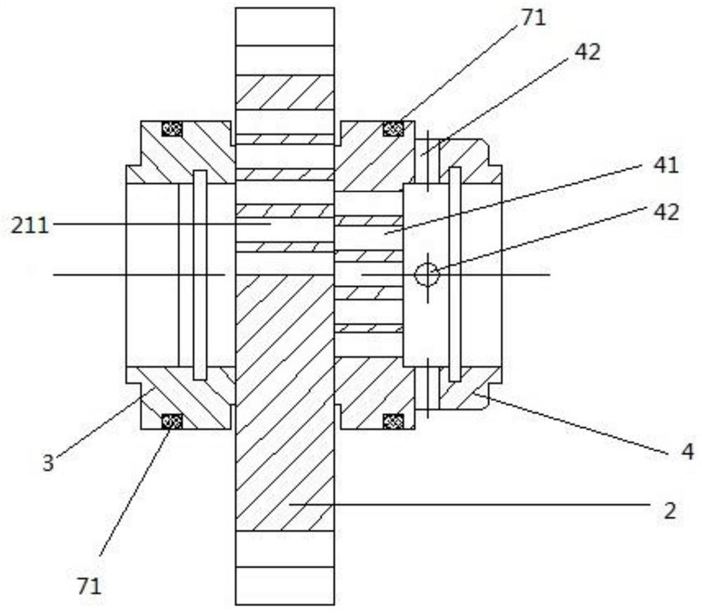
[0051] As a preference, different from the above-mentioned embodiment, such as figure 1 As shown, the left end of the horizontal hole 11 is connected to the high-pressure pipeline (or upstream pipeline), and the right end is connected to the low-pressure pipeline (or downstream pipeline), figure 1 The direction indicated by the arrow is the direction of fluid flow; the left side horizontal hole 111 is close to the position of the valve core 2 and is provided with an annular high-pressure side valve seat 3 whose axis coincides with the horizontal hole 11, and the high-pressure side valve seat 3 Slightly protruding from the right end face of the left horizontal hole 111; the right horizontal hole 112 is provided with a cylindrical low-pressure side valve seat 4 whose axis coincides with the horizontal hole 11 at a position close to the valve core 2. The low-pressure side valve seat 4 protrudes slightly from the left end face of the right horizontal hole 112, and the left side of...
Embodiment 3
[0059] As a preference, different from the above-mentioned embodiments, in the intelligent regulating valve throttling and decompression device of the present invention, the high-pressure side valve seat 3 is flat with the right end surface of the left horizontal hole 111; the low-pressure side valve seat 4 is slightly protruded The left end surface of the right side horizontal hole 112. At this time, the slideway includes the right end surface of the high-pressure side valve seat 3 and the left end surface of the low-pressure side valve seat 4 . The end surface of the high-pressure side valve seat 3 in contact with the valve core 2 and / or the end surface of the low-pressure side valve seat 4 in contact with the valve core 2 is a sealing surface, and the sealing surface is a lapped surface. Welding STL hard alloy, good sealing performance, wear resistance, erosion resistance.
[0060] Alternatively, the high pressure side valve seat 3 is flush with the right end surface of th...
PUM
 Abstract
Description
Claims
Application Information
 - R&D Engineer
- R&D Manager
- IP Professional
- Industry Leading Data Capabilities
- Powerful AI technology
- Patent DNA Extraction
Browse by: Latest US Patents, China's latest patents, Technical Efficacy Thesaurus, Application Domain, Technology Topic, Popular Technical Reports.
© 2024 PatSnap. All rights reserved.Legal|Privacy policy|Modern Slavery Act Transparency Statement|Sitemap|About US| Contact US: help@patsnap.com