Engine connecting rod weighing and pushing device
A technology of engine connecting rod and push device, which is applied in the direction of measuring device, weighing, automatic feeding/discharging weighing equipment, etc., to achieve the effect of avoiding barriers
- Summary
- Abstract
- Description
- Claims
- Application Information
AI Technical Summary
Problems solved by technology
Method used
Image
Examples
Embodiment 1
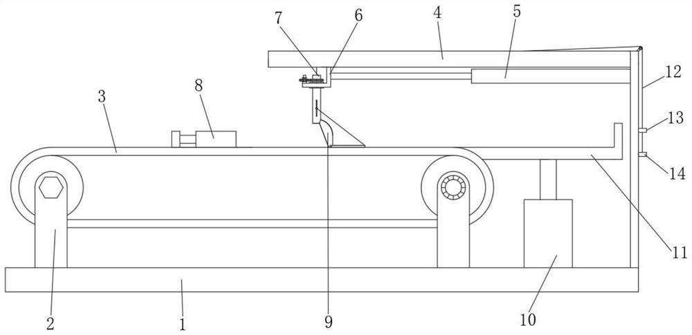
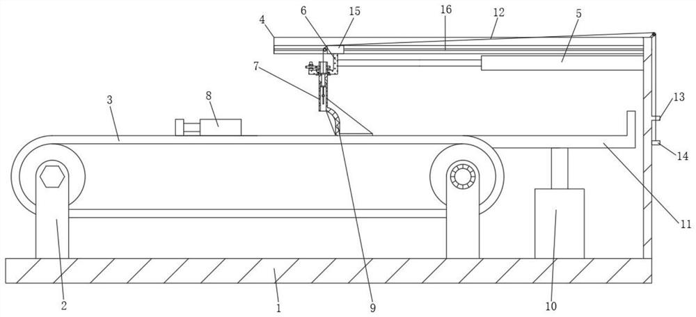
[0030] A weighing and pushing device for an engine connecting rod, comprising a bottom frame 1 and a connecting rod 8, the upper end of the bottom frame 1 is provided with a motor-driven conveyor belt 3, the upper end of the bottom frame 1 is provided with a drive frame 2, and the conveyor belt 3 is installed on the drive frame 2 Above, the lower end of the weighing device 10 is fixedly installed on the chassis 1, the tray 11 at the upper end of the weighing device 10 is connected to the upper end of the conveyor belt 3, the connecting rod 8 is placed on the conveyor belt 3, and the connecting rod 8 is driven by the conveyor belt 3 for horizontal transportation .
[0031] The upper end of the chassis 1 is provided with an upper guide rail 4 parallel to the conveyor belt 3, and one end of the conveyor belt 3 close to the upper guide rail 4 is at the same height as a tray 11 connected to a weighing device 10, and the upper guide rail 4 is equipped with a telescopic rod 5 to drive...
Embodiment 2
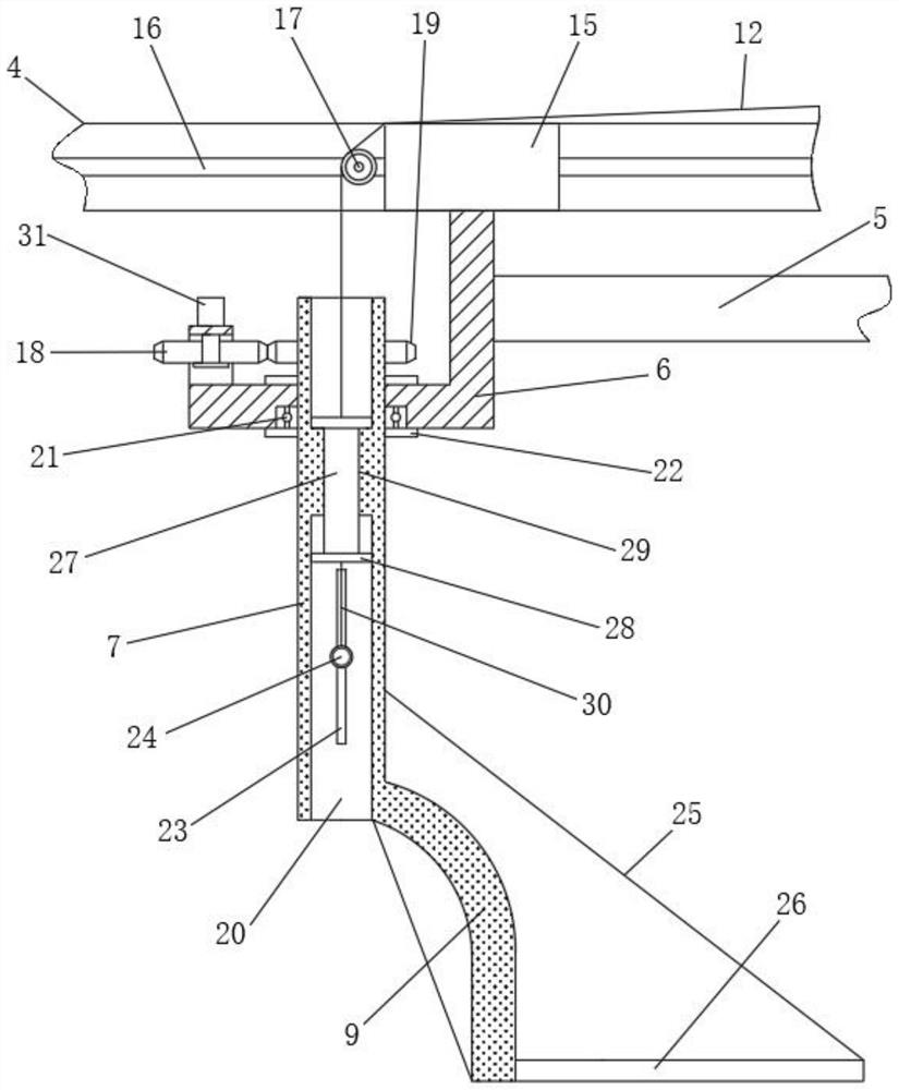
[0037] On the basis of Embodiment 1, in this embodiment, a pair of vertically symmetrical spacer rings 22 are sleeved on the outer wall of the upper end of the rotating tube 7, and the spacer rings 22 distributed up and down are respectively pressed on the upper and lower outer walls of the bracket 6, and rotate The pipe 7 runs through the bracket 6 and is rotatably mounted on the bracket 6 through a bearing 21 .
[0038] For connecting rod assemblies of different heights, the height of the arc-shaped push plate 9 will block the passing position of the connecting rod.
[0039] Utilize limit ring 22 to limit the height of rotating tube 7 on support 6, and then make the arc push plate 9 of rotating tube 7 lower ends be positioned at the upper end of conveyor belt 3, the lower end port of rotating tube 7 is positioned at the upper end of connecting rod 8, makes connecting rod 8 smoothly runs through the lower end of the rotating tube 7, and then utilizes the arc push plate 9 to r...
Embodiment 3
[0041]On the basis of Embodiment 1, this embodiment is provided with a lifting inner cavity 20 that penetrates up and down in the inner cavity of the rotating tube 7, and the middle section of the lifting inner cavity 20 is provided with a lifting groove 29 with an inner diameter smaller than the lifting inner cavity 20. Lifting column 27 is vertically slidably installed in the groove 29, and the upper end of lifting column 27 is connected with upper stay rope 12, and the upper and lower ends of lifting column 27 are respectively provided with limiting plate 28, and one end of upper stay rope 12 is fixed on the upper end of lifting column 27. On the limiting plate 28, the slider 15 is provided with a guide wheel 17, the side plate of the chassis 1 is provided with an ear seat 13, the upper stay cord 12 extends to the ear seat 13 along the guide wheel 17, and the upper stay cord 12 slides Through the ear seat 13, the lower end of the upper pull cord 12 is provided with a baffle ...
PUM
 Abstract
Description
Claims
Application Information
 - R&D Engineer
- R&D Manager
- IP Professional
- Industry Leading Data Capabilities
- Powerful AI technology
- Patent DNA Extraction
Browse by: Latest US Patents, China's latest patents, Technical Efficacy Thesaurus, Application Domain, Technology Topic, Popular Technical Reports.
© 2024 PatSnap. All rights reserved.Legal|Privacy policy|Modern Slavery Act Transparency Statement|Sitemap|About US| Contact US: help@patsnap.com


