
Distribution network differential protection method based on dynamic time bending distance and floating threshold

A technology of dynamic time warping and differential protection, which is applied in the protection of overcurrent response, emergency protection circuit devices, electrical components, etc.

Pending Publication Date: 2022-03-25
WUHAN NARI LIABILITY OF STATE GRID ELECTRIC POWER RES INST
View PDF0 Cites 1 Cited by
  • Summary
  • Abstract
  • Description
  • Claims
  • Application Information

AI Technical Summary

Problems solved by technology

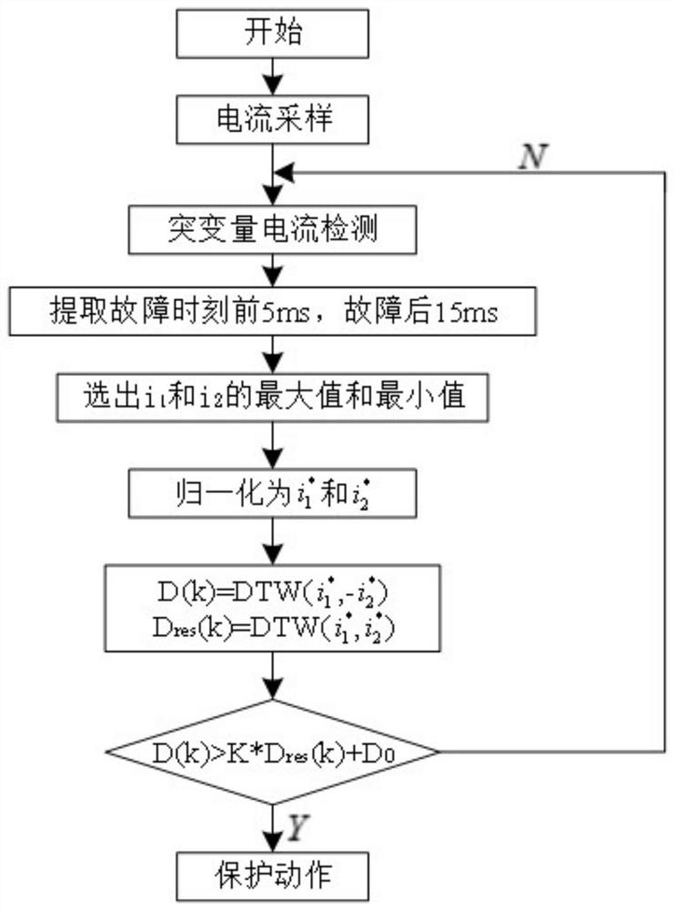
[0005] The purpose of the present invention is to provide a distribution network differential protection method based on dynamic time warping distance and floating threshold. Delay the problem of jitter, and add a floating threshold to prevent the misoperation of the protection, and improve the reliability of the protection

Method used


Image

  • Distribution network differential protection method based on dynamic time bending distance and floating threshold
  • Distribution network differential protection method based on dynamic time bending distance and floating threshold
  • Distribution network differential protection method based on dynamic time bending distance and floating threshold

Examples


Embodiment 1

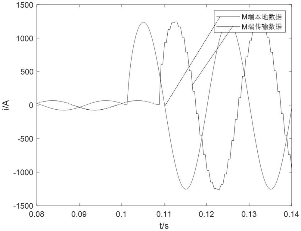
[0052] Example 1: Using Figure 5a The single power supply radial structure in the simulation model, the simulation time is 0.8s. If an internal fault occurs at 0.1s, that is, a fault occurs at f1, and when an external fault occurs at 0.5s, that is, a fault occurs at f2. Monitor the current sampling values ​​of the M side and N side within 0.8s, denoted as i 1 with i 2 , when the mutation current detects the fault, the current on both sides is normalized and recorded as and Thus calculate the DTW example and the main components of the floating threshold, when the criterion D(k)>0.8·D is satisfied res When (k)+5, the protection will act, if it is not satisfied, it will not act. Figure 6a The change law of the faulty phase A when a fault occurs in the two-phase short-circuit area of ​​AB in the single power system. The simulation results show that the DTW distance exceeds the floating threshold at 0.1154s, which proves that a fault has occurred in phase A.

Embodiment 2

[0053] Example 2: Using Figure 5b The closed-loop operation structure in the simulation model, the simulation time is 0.8s. If an internal fault occurs at 0.1s, that is, a fault occurs at f1, and when an external fault occurs at 0.5s, that is, a fault occurs at f2. Monitor the current sampling values ​​of the M side and N side within 0.8s, denoted as i 1 with i 2 , when the mutation current detects the fault, the current on both sides is normalized and recorded as and Thus calculate the DTW example and the main components of the floating threshold, when the criterion D(k)>0.8·D is satisfied res When (k)+5, the protection will act, if it is not satisfied, it will not act. Figure 6b For the closed-loop operation system, when there is a fault in the two-phase short-circuit area of ​​AB, the change law of the fault phase A. The simulation results show that the DTW distance exceeds the floating threshold at 0.1033s, which proves that a fault has occurred in phase A. Figu...


PUM


Abstract

The invention discloses a distribution network differential protection method based on a dynamic time bending distance and a floating threshold. The method comprises the following steps: step 1, current sampling devices at two ends of a protected line in a distribution line carry out current signal sampling at a fixed frequency; step 2, when a current fault detection device detects that the distribution line has a break variable current fault, forming current sampling sequences i1 and i2 by current signals within A milliseconds before a fault moment and B milliseconds after the fault, wherein the current signals are collected by current sampling devices at two ends of a protected line; 3, negation is carried out on the normalized current sequence, and then DTW distance and differential protection floating threshold braking threshold value calculation is carried out on the negated current sequence and the normalized current sequence; and 4, calculating whether the DTW distance and the braking threshold value of the differential protection floating threshold meet the criterion or not. According to the method, the good tolerance of the dynamic time warping algorithm to the time domain is utilized, the floating threshold is added to prevent protection misoperation, and the protection reliability is improved.

Description

technical field [0001] The invention relates to the technical field of distribution network protection, in particular to a distribution network differential protection method based on dynamic time bending distance and floating threshold. Background technique [0002] The direct connection between the distribution network and users is the key link to ensure the quality of power supply, improve the operating efficiency of the power system and the ability to accept renewable energy. Most of the traditional distribution network is a single power source radial structure, the load type is usually a traditional load, and the boundary between source-network-load is very clear. With the development of the distribution network and changes in user needs, distributed power generation is gradually connected to the distribution network, and the boundaries of source-network-load become blurred. After the distributed power generation is connected, the fault characteristics of the distributi...

Claims


Application Information

Patent Timeline
IPC IPC(8): H02H7/26H02H3/08
CPCH02H7/26H02H3/08
Inventor 龙威顾然李穆宋友邓建钢谷凯凯彭仲晗胡锦亮曹磊
Owner WUHAN NARI LIABILITY OF STATE GRID ELECTRIC POWER RES INST
Learn More