


Quick Research
Generate reliable direction feasibility study reports for your R&D in just a few steps.

Technical Q&A
Discover and master advanced knowledge NOW. Basics, ideas, possibilities, all at once.

Find Solutions
As an expert in R&D theories, this can generate solutions to your technical problems instantly.

Evaluate Feasibility
Analyze your overall solution with one click, know your potential R&D risks in advance.

Monitor Landscape
Get weekly tech updates, stay abreast of the latest tech innovations and key insights.
Beam-combining and beam-splitting illumination system
A lighting system and light-splitting technology, applied in the field of lighting, can solve the problems of large volume and low efficiency of composite beams
- Summary
- Abstract
- Description
- Claims
- Application Information
AI Technical Summary
Problems solved by technology
Method used
Image

Examples
Embodiment 1
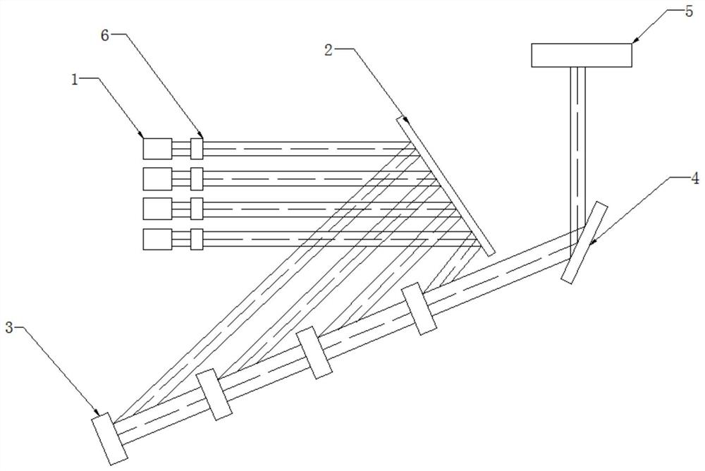
[0025] A beam combining and splitting lighting system, comprising a plurality of light source modules-1, a collimation module 6, a light splitting module 2 and a plurality of beam combining modules-3, the plurality of light source modules-1 are located on the incident side of the collimation module 6, And the parallel light beam that light source module one 1 emits by collimation module 6 enters in the incidence surface of beam splitting module 2, and the angle of described beam splitting module 2 is less than 30 °, adopts the light combination design less than 30 °, reduces the light combining mirror (light splitter) Mirror) processing difficulty, thereby reducing costs. It is of great benefit to the light combination of light sources with small main wavelength spacing, and the design of the mixed wave light source greatly reduces the size of the system. The light splitting module 2 is used to emit light beams into the incident surface of the beam combining module 3 , the bea...
Embodiment 2
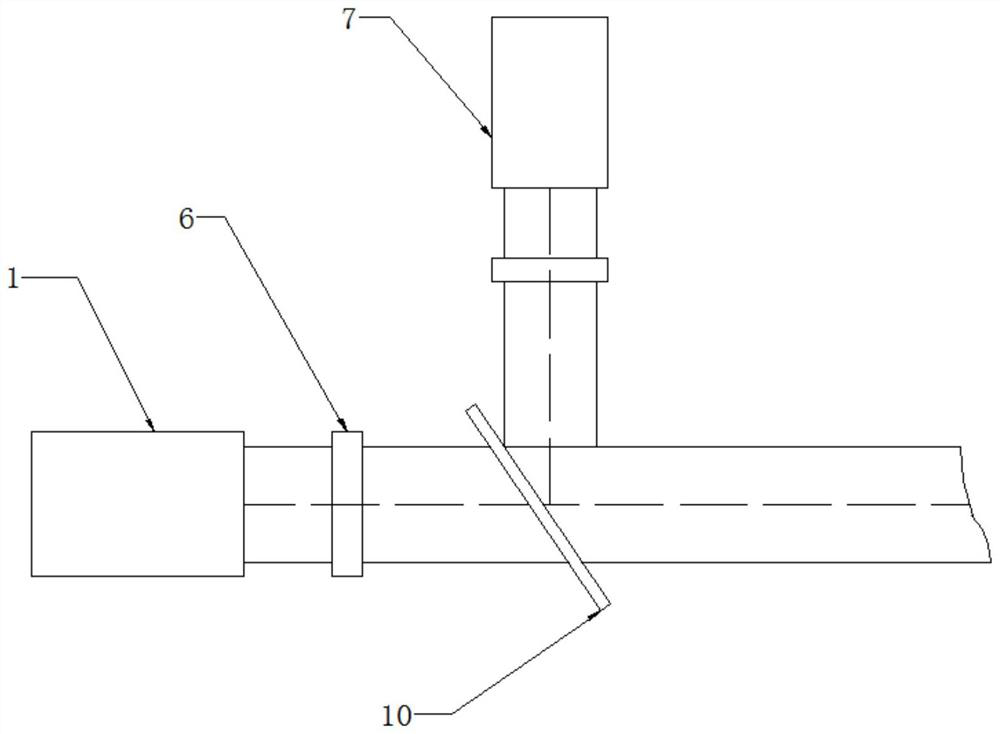
[0029] A beam combining and splitting lighting system, comprising a light source module 1, a collimation module 6, a beam combining module 10 and a light source module 2 7, the light source module 1 is located on the incident side of the collimation module 6, and the light source module 1 passes through The parallel light beam emitted by the collimation module 6 enters the incident surface of the beam combining module 10, the light source module 2 7 is located on the other incident side of the beam combining module 10, and the light beam emitted by the light source module 2 7 is perpendicular to the light source module 1 1 The light beam emitted by the first light source module 1 and the light beam emitted by the second light source module 7 are synthesized into parallel light beams by the beam combining module 4 10, and the beam combining module 4 10 is a dichroic mirror.
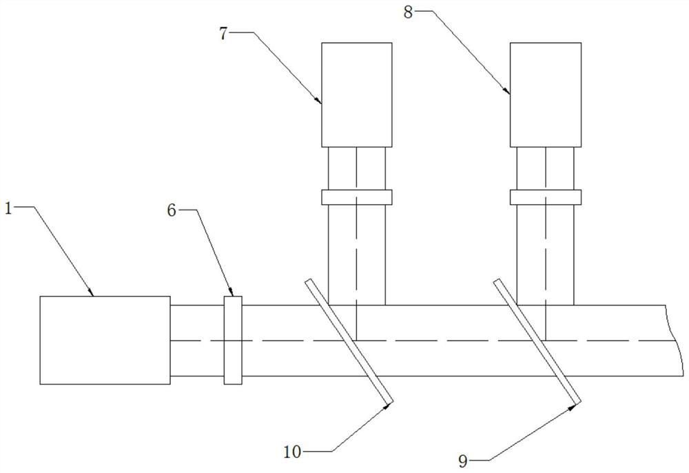
[0030] see image 3 , the present invention provides a technical solution:
Embodiment 3
[0032] A beam combining and splitting lighting system, comprising a light source module 1, a collimation module 6, a beam combining module 10, a light source module 2 7, a light source module 3 8 and a beam combining module 3 9, the beam combining module 4 10 combines the light source A parallel beam is synthesized by the two beams of module one 1 and light source module two 7, and the parallel beam emitted by the beam combining module four 10 is located on the incident surface of the beam combining module three 9, and the beam emitted by the light source module three 8 is perpendicular to the beam combining The parallel beam emitted by the module four 10, the beam combining module three 9 combines the parallel beam emitted by the beam combining module four 10 and the beam emitted by the light source module three 8 to realize the output in the way of beam overlapping, and the power is increased while the beam quality remains unchanged.
PUM
| Property | Measurement | Unit |
|---|---|---|
| Wavelength | aaaaa | aaaaa |
Abstract
Description
Claims
Application Information
 - R&D Engineer
- R&D Manager
- IP Professional
- Industry Leading Data Capabilities
- Powerful AI technology
- Patent DNA Extraction
Browse by: Latest US Patents, China's latest patents, Technical Efficacy Thesaurus, Application Domain, Technology Topic, Popular Technical Reports.
© 2024 PatSnap. All rights reserved.Legal|Privacy policy|Modern Slavery Act Transparency Statement|Sitemap|About US| Contact US: help@patsnap.com