Totally-closed low-speed permanent magnet direct drive system for electric gate valve

A permanent magnet direct drive, electric gate valve technology, applied in the direction of sliding valves, valve details, valve devices, etc., can solve the problems of gate valve stroke limitation, large starting current, polluted medium, etc., to ensure accuracy and reliability, and reduce work Energy consumption, the effect of improving work efficiency

Pending Publication Date: 2022-03-25
LIAONING WUHUAN SPECIAL MATERIALS & INTELLIGENT EQUIP IND TECH RES INST CO LTD
View PDF7 Cites 0 Cited by
  • Summary
  • Abstract
  • Description
  • Claims
  • Application Information

AI Technical Summary

Problems solved by technology

[0003] At present, in the existing valve drive technology, the fully enclosed shielded drive structure has been widely used. For example, the invention patent No. 201710203884.4 is a rotary valve drive device with a sealed shield The electromagnetic force of the magnet makes the valve stem rotate 90° synchronously, and the stroke is limited for the gate valve; the upper and lower parts of the shielding structure are sealed, and the permanent magnet has not been specially selected and treated. These design methods are difficult to meet the requirements of high temperature, high pressure and corrosive media. use environment
The utility model patent with the patent number of 201020231772.3 is an electric gate valve electric transmission device with a fully shielded structure, but its driving mode is an asynchronous deceleration driving mode of "squirrel cage rotor + reducer". This design mode has a large starting current and cannot realize the valve Precise opening and closing, long transmission chain, and the copper or aluminum of the squirrel cage rotor is very easy to react with high-temperature medium, polluting the medium in the valve body

Method used


Image

  • Totally-closed low-speed permanent magnet direct drive system for electric gate valve

Examples


Embodiment Construction

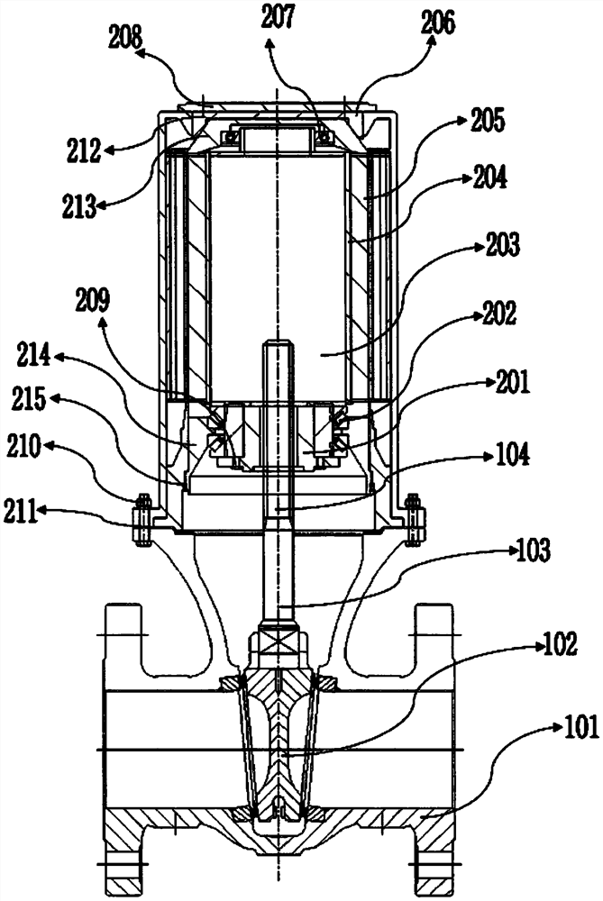
[0030] As shown in the accompanying drawings, a fully enclosed low-speed permanent magnet direct drive system for an electric gate valve according to the present invention includes a casing assembly, a stator 205, a non-magnetic shielding casing 204, a rotor assembly 203 and a control assembly, and the stator 203 is embedded in the In the casing assembly, the outer wall of the stator 203 is close to the inner wall of the casing shell 206, and the position of the stator 203 is limited by the shoulder of the non-magnetic shielding shell; the non-magnetic shielding shell 204 is located between the stator 205 and the rotating assembly, and is fixed on the casing The housing 206 shields the rotor assembly and the lead screw 104 inside its cavity. The rotor assembly transmits the torque to the lead screw 104 connected above the gate 102 through the screw nut 201, which drives the gate 102 to move up and down along the axis of the rotor assembly. The entire movement process uses a PLC...


PUM


Abstract

The invention discloses a totally-closed low-speed permanent magnet direct drive system for an electric gate valve, a drive system connected with a lead screw is arranged above a valve body, and the drive system comprises a machine shell assembly, a stator, a non-magnetic shielding shell, a rotor assembly and a control assembly; the stator is arranged on the inner side of the machine shell assembly, the non-magnetic shielding shell is arranged on the inner side of the stator, the rotor assembly is arranged on the inner side of the non-magnetic shielding shell, and the rotor assembly is connected with the lead screw. The upper end of the non-magnetic shielding shell is connected with the machine shell assembly, the lower end of the non-magnetic shielding shell is fixed to the machine shell assembly, and the control assembly is used for controlling the whole action process of the valve body inner flashboard so that the flashboard can be opened or closed. Accurate opening and closing control over the valve is achieved, the working efficiency of the valve is improved, the working energy consumption of the valve is reduced, and a lengthy transmission chain of an existing asynchronous motor is omitted.

Description

technical field [0001] The invention belongs to the technical field of driving electric gate valves applied in the environment of high temperature, high pressure and anti-leakage medium, and in particular relates to a fully enclosed low-speed permanent magnet direct drive system for electric gate valves. Background technique [0002] Valve is an important component device in the process of fluid transportation. It is widely used in various industries, mainly in the fields of petroleum, petrochemical, chemical, metallurgy, electric power, water conservancy, urban construction, fire protection, machinery, coal, food and ships. Among them, gate valves are mainly used in important fields such as chemical industry, nuclear power, and ships, especially in devices and equipment for transporting and containing high-temperature, high-pressure, high-radioactive, and highly toxic media. requirements are more stringent. [0003] At present, in the existing valve drive technology, the f...

Claims


Application Information

Patent Timeline
Patent Type & Authority Applications(China)
IPC IPC(8): F16K31/08F16K31/04F16K3/12F16K3/36F16K49/00
CPCF16K31/08F16K31/0668F16K31/047F16K3/12F16K3/36F16K49/00
Inventor 李嘉于伟东张吉张威刘春明张宪伟张俊飞李雷
Owner LIAONING WUHUAN SPECIAL MATERIALS & INTELLIGENT EQUIP IND TECH RES INST CO LTD
Why Eureka
Try Eureka