
Mechanical tensioning device for electromechanical transmission belt

A technology of electromechanical transmission and tensioning device, applied in the direction of transmission device, mechanical equipment, belt/chain/gear, etc., can solve the problems of poor adjustability, potential safety hazards, poor stability, etc., and achieve the effect of improving adjustability

Pending Publication Date: 2022-03-25
QINGDAO UNIV OF SCI & TECH
View PDF9 Cites 0 Cited by
  • Summary
  • Abstract
  • Description
  • Claims
  • Application Information

AI Technical Summary

Problems solved by technology

[0007] The purpose of the present invention is to provide a mechanical tensioning device for electromechanical transmission belts to solve the problem that the current mechanical tensioning devices for electromechanical transmission belts proposed in the background technology have poor stability during use and cannot meet the needs of larger electromechanical equipment belts. Tensioning, so there is a certain potential safety hazard during use. The current electromechanical drive belt mechanical tensioning device has poor adjustability and cannot be adjusted according to the demand, so there is some inconvenience in use. The current electromechanical belt The mechanical tensioning device of the transmission belt is not easy to install on the electromechanical equipment during use, so it is not convenient to fix the transmission belt after tensioning, which may lead to the problem that the tension of the transmission belt is not firm

Method used


Image

  • Mechanical tensioning device for electromechanical transmission belt
  • Mechanical tensioning device for electromechanical transmission belt
  • Mechanical tensioning device for electromechanical transmission belt

Examples


Embodiment Construction

[0027] The following will clearly and completely describe the technical solutions in the embodiments of the present invention with reference to the accompanying drawings in the embodiments of the present invention. Obviously, the described embodiments are only some, not all, embodiments of the present invention. Based on the embodiments of the present invention, all other embodiments obtained by persons of ordinary skill in the art without making creative efforts belong to the protection scope of the present invention.

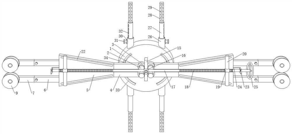
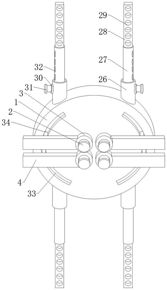
[0028] see Figure 1-6, the present invention provides a mechanical tensioning device for an electromechanical transmission belt, comprising a circular plate 1, four support shafts 2 are fixedly arranged on the front side wall of the circular plate 1, and the four support shafts 2 are passed through the four support shafts 2, and the four support shafts The shafts 4 are arranged in a rectangle, and through the rotating sleeve 3 set on the four supporting shaft...


PUM


Abstract

The invention discloses an electromechanical transmission belt mechanical tensioning device, and relates to the field of transmission belt tensioning devices, the electromechanical transmission belt mechanical tensioning device comprises a circular plate, four supporting shafts are fixedly arranged on the front side wall of the circular plate, and rotating sleeves are rotationally connected to the four supporting shafts through first bearings. Four supporting shafts are arranged on a circular plate, rotating sleeves are connected with the supporting shafts in a sleeving mode, a supporting part formed by a transverse plate, a trapezoidal plate, a first butt joint plate and a second butt joint plate can be rotated, and then a sliding groove formed in the trapezoidal plate is slidably connected with a linkage sliding rod; two threaded cylinders are close to each other on an adjusting rod, the threaded cylinders can drive a linkage sliding rod to slide in a sliding groove through a linkage rod, and at the moment, due to the fact that the sliding groove is obliquely formed, the left sides of two trapezoidal plates on the left side and the right sides of two trapezoidal plates on the right side can be far away from each other; and then the two belt wheels on the left side and the two belt wheels on the right side can be driven to be far away from each other, and the loose transmission belt is tensioned.

Description

technical field [0001] The invention relates to a mechanical tensioning device, in particular to an electromechanical transmission belt mechanical tensioning device. Background technique [0002] The belt drive is a tensioned (ring-shaped) belt that is set on the pulleys of the two transmission shafts. It relies on the friction generated when the belt and the pulleys are tensioned to transmit the power of one shaft to the other shaft. The belt rotation can be used It is used for large-distance transmission between two shafts (working machine and power machine). Because the belt is elastic, it can ease the impact, reduce vibration, and the transmission is stable, but it cannot maintain a strict transmission ratio (the number of revolutions per minute of the driving wheel is equal to the number of revolutions per minute of the driven wheel. The ratio of the number of revolutions), when the transmission part encounters an obstacle or is overloaded, the belt will slip on the pul...

Claims


Application Information

Patent Timeline
Patent Type & Authority Applications(China)
IPC IPC(8): F16H7/10F16H7/08
CPCF16H7/10F16H7/08F16H2007/0842F16H2007/0865F16H2007/0891F16H2007/0895
Inventor 续敏段俊勇李向荣
Owner QINGDAO UNIV OF SCI & TECH
Learn More