
Floor slab edge reverse ridge formwork and erecting method thereof

A formwork and floor slab technology, applied in the field of anti-sill formwork at the edge of the floor slab and its support, can solve the problems of slow erection efficiency, high safety risks, and long labor time, so as to reduce the working time at the edge, reduce safety risks, The effect of improving support efficiency

Pending Publication Date: 2022-03-25
CHINA CONSTR STEEL STRUCTURE CORP LTD
View PDF0 Cites 0 Cited by
  • Summary
  • Abstract
  • Description
  • Claims
  • Application Information

AI Technical Summary

Problems solved by technology

This formwork system is slow to set up and takes a long time
And the anti-sill formwork is erected on the edge of the floor for high-altitude operations on the edge. The longer the construction time, the greater the safety risk of workers during construction.

Method used


Image

  • Floor slab edge reverse ridge formwork and erecting method thereof
  • Floor slab edge reverse ridge formwork and erecting method thereof
  • Floor slab edge reverse ridge formwork and erecting method thereof

Examples


Embodiment Construction

[0030] Embodiments of the present application are described in detail below, and examples of the embodiments are shown in the drawings, wherein the same or similar reference numerals denote the same or similar elements or elements having the same or similar functions throughout. The embodiments described below by referring to the figures are exemplary, and are only for explaining the present application, and should not be construed as limiting the present application.

[0031] In the description of the present application, it should be understood that the orientation descriptions, such as the orientation or positional relationship indicated by up, down, left, right, front, back, etc., are based on the orientation or positional relationship shown in the drawings, and only In order to facilitate the description of the present application and simplify the description, it does not indicate or imply that the device or element referred to must have a specific orientation, be construc...


PUM

PropertyMeasurementUnit
Thicknessaaaaaaaaaa

Abstract

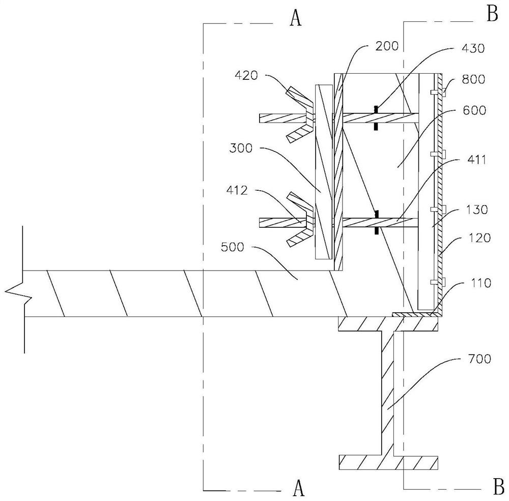
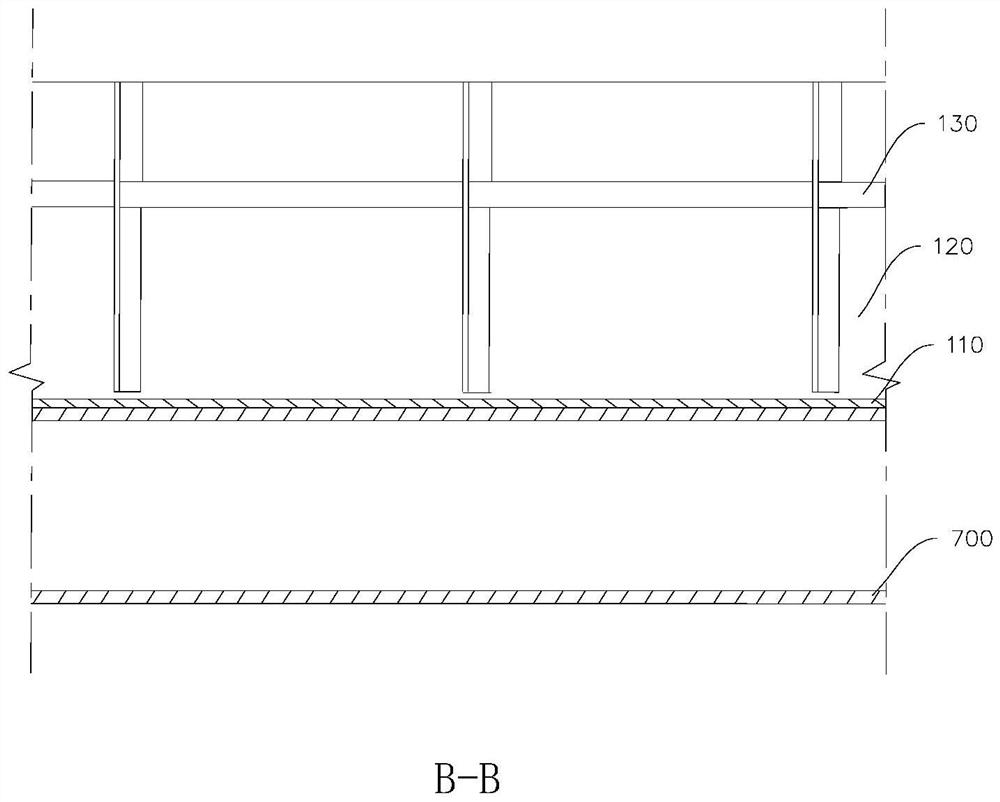
The invention discloses a floor edge reverse ridge formwork and a supporting method thereof. The floor edge reverse ridge formwork comprises an outer side formwork, an inner side formwork, a first keel and split bolts. The outer side formwork edge sealing formwork comprises a bottom edge and side edges, the bottom edge is used for being fixed to a steel beam, the side edges are perpendicularly connected to the bottom edge, and the height of the side edges is the sum of the thickness of a floor slab and the height of a reverse ridge; the inner side template is parallel to the side edge; the first keel is located on the side, away from the side edge, of the inner formwork. The split bolt comprises a screw rod and a fixing nut, one end of the screw rod is connected to the outer side formwork, the other end of the screw rod sequentially penetrates through the inner side formwork and the first keel, and the fixing nut is connected to the screw rod in a threaded mode and located on the side, away from the inner side formwork, of the first keel. The edge sealing die can serve as a template edge sealing structure during pouring of a floor slab and a reverse ridge at the same time, the bottom edge is fixed to the steel beam, a pouring template can be set up more easily, the edge work time of workers is shortened, the erecting efficiency of the reverse ridge template is improved, and the safety risk of construction is reduced.

Description

technical field [0001] The present application relates to the technical field of concrete floor slabs, in particular to a reverse sill formwork at the edge of a floor slab and a supporting method thereof. Background technique [0002] In order to meet the various functions of building construction, some anti-sills are often designed on the edges of the floor slabs, which are used as parapet walls, curtain wall anti-sills, water-retaining anti-sills, and railing anti-sills. This type of anti-sill is usually in the form of cast-in-place reinforced concrete with the same material as the floor slab, so it is necessary to support the anti-sill formwork on the edge of the floor after the construction of the concrete floor slab is completed. In the traditional building structure, after the floor is poured, the workers clamp the outer formwork on the side of the floor with formwork keels, then use the pull bolts and another formwork keel to lock the outer formwork, and set the inner...

Claims


Application Information

Patent Timeline
IPC IPC(8): E04G13/00E04G17/00E04G17/065
CPCE04G13/00E04G17/00E04G17/0655
Inventor 蔡东鹏肖合顺林经雄陈迟田生满陈金滨朱洋陈霖霖
Owner CHINA CONSTR STEEL STRUCTURE CORP LTD
Learn More