
Digging laneway temporary support device

A temporary support and roadway technology, applied in cutting machinery, earthwork drilling, cutting machinery, etc., can solve the problems of high roof pressure, roof separation, easy breakage, etc., to achieve large initial support force and high safety , the effect of reducing labor intensity

Inactive Publication Date: 2009-01-07
HUAYANG NEW MATERIAL TECH GRP CO LTD
View PDF1 Cites 10 Cited by
  • Summary
  • Abstract
  • Description
  • Claims
  • Application Information

AI Technical Summary

Problems solved by technology

[0005] The purpose of the present invention is to solve the problem that the broken coal roof of the mine is developed due to the development of the geological structure, and the excavated roadway roof has high pressure and is easy to break, resulting in the problem that the roof is easily separated from the layer and caving if the distance between the roof and the roof is more than 2 meters. A temporary support device for tunneling roadway

Method used


Image

  • Digging laneway temporary support device
  • Digging laneway temporary support device
  • Digging laneway temporary support device

Examples


Embodiment Construction

[0015] specific implementation plan

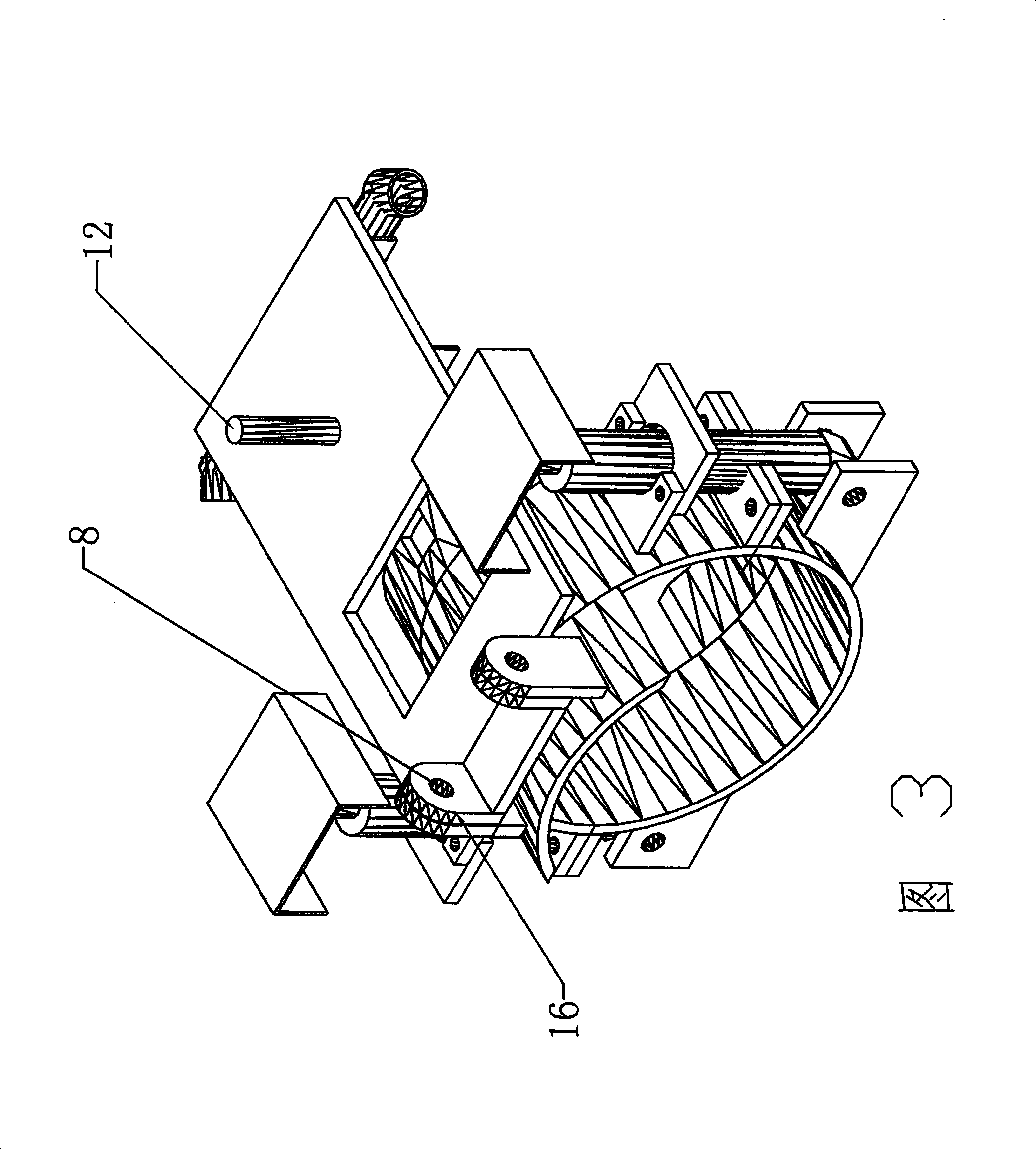
[0016] Describe as follows in conjunction with accompanying drawing: the bracket 1 that the solid line part of accompanying drawing 1 shows is the state schematic diagram when implementing the temporary support operation, the hydraulic jack of the dotted line part has shown the state of the temporary support roof; the bracket 1 shown in the dotted line part 1 It is a schematic diagram of the flipped state during the tunneling operation of the roadheader. The bracket in the flipped state will not affect the tunneling operation of the roadheader operator. The bracket can be deployed forward or turned backward with the shaft pin 8 as the axis, which can be implemented manually.

[0017] The roadway temporary support devices of the present invention are all made of steel materials. The thickness of the steel plate used for the bracket 1 and the fastening ring 2 is not less than 20 mm. A hole on the boss of the oil injection hole of the arm ha...


PUM


Abstract

The present invention relates to a drivage temporary supporting device which belongs to the drivage supporting machinery and solves the problems that a top plate is delaminated and collapsed easily if the unsupported roof distance of a new drivage is more than two meters due to the geological structural development of the top plate of a mine. The drivage temporary supporting device is characterized in that the supporting device is installed at the telescopic boom of a roadheader by a fastening ring. The upper ring edge and the lower ring edge of the fastening ring are provided with connecting boards for installing and fixing. The bottom of the lower ring of the fastening ring is provided with a support pedestal. The two ends of the support pedestal are symmetrically and vertically connected with lifting hydraulic jacks. The tops of a pair of lifting pillars of the hydraulic jacks are provided with saddles. The connecting boards which are used for fixing the hydraulic jacks are symmetrically arranged at the two sides of a wall which is vertical to the upper ring arc line of the fastening ring. Shafting brackets are symmetrically arranged at the arc line at the front part of the upper ring of the fastening ring vertical to the axial line of the telescopic boom. The shafting brackets are matched with an engaging lug at the back end of a bracket and are connected by a pin roll. A whiffletree is arranged at the front section of the face of the bracket which is connected with the fastening ring by the pin roll. A bracket slot is arranged at the inner side of the whiffletree. A hollow frame is dug at the middle section of the bracket, and the back of the bracket is provided with a support leg.

Description

technical field [0001] The invention belongs to tunneling roadway support machinery, and in particular relates to installing a tunneling roadway temporary support device on a tunneling machine for mine mechanized construction. Background technique [0002] With the acceleration of mine roadway mechanized excavation speed and the improvement of excavation efficiency, the roadway formed by the excavation face needs to be supported quickly. Before the permanent support is completed, temporary support must be erected to ensure that the newly excavated Before the permanent support of the roadway is completed, the roof of the roadway must not have separation, deformation and roof fall, which will affect safe production. [0003] The general temporary support is manually supported, especially in the roadway where the pressure of the excavation roadway is high and the distance between the roof and the roof cannot exceed 2 meters (note: if the distance between the roof and the roof i...

Claims


Application Information

Patent Timeline
Patent Type & Authority Applications(China)
IPC IPC(8): E21C35/04E21C25/06
Inventor 梁贵生
Owner HUAYANG NEW MATERIAL TECH GRP CO LTD
Learn More