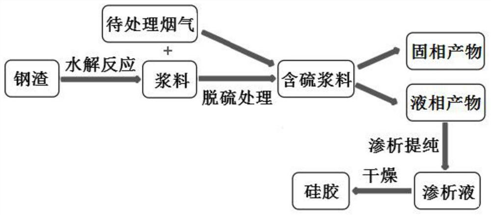
Method for synergistically extracting silica gel by removing SO2 in flue gas through steel slag
A flue gas and steel slag technology, applied in the field of industrial waste recycling, can solve the problems of inability to realize the resource utilization of desulfurization products, the comprehensive utilization rate of resources is less than 25%, occupying land and other problems, so as to realize the utilization of resources and avoid silica gel Structural damage and low SO2 effect
- Summary
- Abstract
- Description
- Claims
- Application Information
AI Technical Summary
Problems solved by technology
Method used
Image

Examples
Embodiment 1
[0075] Mix 10 g of steel slag with a median particle size of 3.15 μm and 100 mL of water, and carry out a hydrolysis reaction at 50 ° C and 380 rpm for 5 min to obtain a slurry;
[0076] The simulated flue gas is prepared by the simulated flue gas system, where SO 2 and O 2 The volume ratio is 1:1, SO 2 and SO 2 Gas distribution balance gas N 2 The volume ratio is 5:95, O 2 and O 2 Gas distribution balance gas N 2 The volume ratio is 25:75, and the flue gas is passed into the device equipped with the slurry at a flow rate of 0.8mL / min, and the desulfurization treatment of the flue gas occurs in the device for 0.5h, wherein, the flue gas desulfurization treatment device The gas concentration at the inlet and outlet is detected by a flue gas analyzer to obtain a sulfur-containing slurry;
[0077] Suction filtering the sulfur-containing slurry to obtain a solid phase and a liquid phase;
[0078] Put the obtained liquid phase in a dialysis bag with a molecular weight cut-o...
Embodiment 2
[0085] Mix 10 g of steel slag with a median particle size of 3.15 μm and 100 mL of water, and carry out a hydrolysis reaction at 50 ° C and 380 rpm for 10 min to obtain a slurry;
[0086] The simulated flue gas is prepared by the simulated flue gas system, where SO 2 and O 2 The volume ratio is 1:1, SO 2 and SO 2 Gas distribution balance gas N 2 The volume ratio is 5:95, O 2 and O 2 Gas distribution balance gas N 2 The volume ratio of the slurry is 25:75, and the flue gas is passed into the device equipped with the slurry at a flow rate of 1.2mL / min, and the desulfurization treatment of the flue gas occurs in the device for 1 hour, wherein, the inlet of the flue gas desulfurization treatment device The gas concentration at the outlet is detected by a flue gas analyzer to obtain a sulfur-containing slurry;
[0087] Suction filtering the sulfur-containing slurry to obtain a solid phase and a liquid phase;
[0088] Put the obtained liquid phase in a dialysis bag with a mo...
Embodiment 3
[0091] Mix 10 g of steel slag with a median particle size of 4.63 μm and 50 mL of water, and carry out a hydrolysis reaction at 60°C and 380 rpm for 10 minutes to obtain a slurry;
[0092] The simulated flue gas is prepared by the simulated flue gas system, where SO 2 and O 2 The volume ratio is 1:1, SO 2 and SO 2 Gas distribution balance gas N 2 The volume ratio is 5:95, O 2 and O 2 Gas distribution balance gas N 2 The volume ratio of the slurry is 25:75, and the flue gas is passed into the device equipped with the slurry at a flow rate of 1.2mL / min, and the desulfurization treatment of the flue gas occurs in the device for 1 hour, wherein, the inlet of the flue gas desulfurization treatment device The gas concentration at the outlet is detected by a flue gas analyzer to obtain a sulfur-containing slurry;
[0093] Suction filtering the sulfur-containing slurry to obtain a solid phase and a liquid phase;
[0094] Put the obtained liquid phase in a dialysis bag with a m...
PUM
| Property | Measurement | Unit |
|---|---|---|
| particle size | aaaaa | aaaaa |
| specific surface area | aaaaa | aaaaa |
| specific surface area | aaaaa | aaaaa |
Abstract
Description
Claims
Application Information
 - R&D
- Intellectual Property
- Life Sciences
- Materials
- Tech Scout
- Unparalleled Data Quality
- Higher Quality Content
- 60% Fewer Hallucinations
Browse by: Latest US Patents, China's latest patents, Technical Efficacy Thesaurus, Application Domain, Technology Topic, Popular Technical Reports.
© 2025 PatSnap. All rights reserved.Legal|Privacy policy|Modern Slavery Act Transparency Statement|Sitemap|About US| Contact US: help@patsnap.com