Developing device and method for vehicle A-column image collected along with sight line

An image and vehicle technology, applied in the field of vehicle A-pillar image developing device, can solve the problem of inability to display blind spot images, and achieve the effects of stable and reliable system operation, high accuracy, and improved accuracy and speed.

Pending Publication Date: 2022-03-25
惠州市炬能量电子科技有限公司
View PDF0 Cites 3 Cited by
  • Summary
  • Abstract
  • Description
  • Claims
  • Application Information

AI Technical Summary

Problems solved by technology

[0004] The object of the present invention is to provide a vehicle A-pillar image development device and method for acquisition following line of sight, to obtain the A-pillar blind area image according to the driver's head posture and human eye position, and perform perspective on the acquired A-pillar blind area image Changing and adjusting the picture angle solves the problem that the existing A-pillar blind spot elimination system cannot dynamically display the blind spot image according to the change of the driver's line of sight.

Method used


Image

  • Developing device and method for vehicle A-column image collected along with sight line
  • Developing device and method for vehicle A-column image collected along with sight line
  • Developing device and method for vehicle A-column image collected along with sight line

Examples


Embodiment Construction

[0033] The following will clearly and completely describe the technical solutions in the embodiments of the present invention with reference to the accompanying drawings in the embodiments of the present invention. Obviously, the described embodiments are only some, not all, embodiments of the present invention. Based on the embodiments of the present invention, all other embodiments obtained by persons of ordinary skill in the art without making creative efforts belong to the protection scope of the present invention.

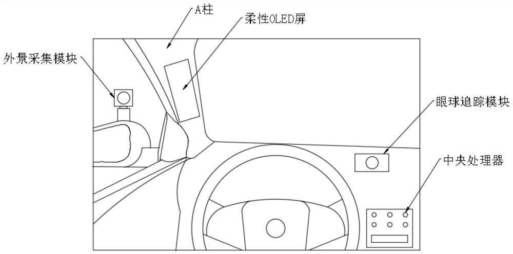
[0034] see Figure 1-3 , the present invention provides a technical solution: a vehicle A-pillar image developing device that follows line of sight acquisition, including a flexible OLED screen, an eye tracking module, an exterior scene acquisition module, and a central processing unit, and the flexible OLED screens are respectively installed inside the car On the A-pillars on both sides, the eye tracking module is installed on the inner wall of the car in fro...


PUM


Abstract

The invention discloses a vehicle A column image developing device capable of collecting following sight, which comprises flexible OLED screens, an eyeball tracking module, an exterior scene collecting module and a central processing unit, the flexible OLED screens are respectively mounted on A columns on two sides in a vehicle, the eyeball tracking module is mounted on the inner wall of the vehicle in front of a driving position, and the exterior scene collecting module is mounted on the inner wall of the vehicle in front of the driving position. The eyeball tracking module and the exterior scene acquisition modules are installed on two sets of rearview mirrors outside an automobile respectively, the central processing unit is packaged in the automobile, the eyeball tracking module and the exterior scene acquisition modules are electrically connected with the central processing unit, the central processing unit is electrically connected with the flexible OLED screen, and the flexible OLED screen is electrically connected with the eyeball tracking module and the exterior scene acquisition modules. The A-column blind area image is obtained according to the head posture and the eye position of the driver, and the problems that an existing A-column blind area eliminating system cannot dynamically display the blind area image according to the sight change of the driver, and a certain angle exists between an image boundary and an external actual image are solved.

Description

technical field [0001] The present invention relates to the technical field of driving safety technology, in particular to a vehicle A-pillar image development device that follows line of sight acquisition, and also relates to a vehicle A-pillar image development method that follows line of sight acquisition. Background technique [0002] The A-pillar of a car is the load-bearing pillar connecting the front windshield glass and the cockpit door of the car. It ensures the structural safety of the car body, but it also blocks the driving line of sight to a certain extent, especially when the driver is turning or changing lanes. . However, the traditional methods range from opening triangular windows on the A-pillar, installing reversing stickers, to the current blind spot warning system, installing cameras or radars. Although these methods can eliminate the blind spot of the A-pillar to a certain extent, there are still many problems. , such as reversing stickers, which are c...

Claims


Application Information

Patent Timeline
Patent Type & Authority Applications(China)
IPC IPC(8): B60R1/25
CPCB60R1/00B60R2300/202B60R2300/8026
Inventor 王海鹏赵雷庄利然
Owner 惠州市炬能量电子科技有限公司
Why Eureka
Try Eureka