
Clamping system

A clamping and end face technology, applied in the field of tooling and fixtures, can solve the problems of lower production efficiency, high use cost, and cost increase, and achieve the effects of improving processing efficiency, reducing processing time, and avoiding shaking

Inactive Publication Date: 2022-03-25
孙璐
View PDF0 Cites 2 Cited by
  • Summary
  • Abstract
  • Description
  • Claims
  • Application Information

AI Technical Summary

Problems solved by technology

[0002] The processing and manufacturing industry is inseparable from metal cutting machine tools, and fixtures can improve machining accuracy, production efficiency, and reduce labor intensity. There are differences in the appearance of different types of parts, and there are strict requirements on fixtures in all aspects of size and shape, and special designs are often adopted. Fixtures, and special fixtures are too costly for the design and use of small batches of parts, and the characteristics of low reuse rate will lead to a substantial increase in costs and reduce production efficiency. Trial production and production of small batches of parts will make the clamping process more complicated. Professionals need to be used, and the fixtures must meet the stability and reliability of workpiece positioning during use, so a device to solve the above problems is needed

Method used


Image

  • Clamping system
  • Clamping system
  • Clamping system

Examples


Embodiment Construction

[0023] The following will clearly and completely describe the technical solutions in the embodiments of the present invention with reference to the accompanying drawings in the embodiments of the present invention. Obviously, the described embodiments are only some, not all, embodiments of the present invention. Based on the embodiments of the present invention, all other embodiments obtained by persons of ordinary skill in the art without creative work fall within the protection scope of the present invention:

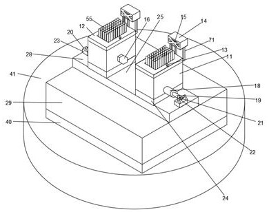
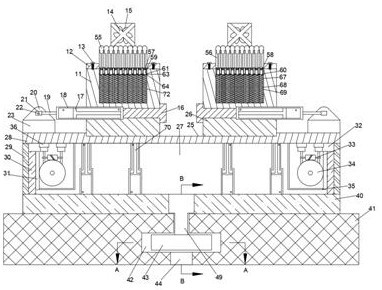
[0024] Refer to attached Figure 1-Figure 8, a clamping system according to an embodiment of the present invention, comprising a main box body 41, the upper end surface of the main box body 41 is rotated with a rotating plate 40, and the lower end surface of the rotating plate 40 is closely attached to the main box body 41 The inner circle of the center of the rotating plate 40 is rotatably connected with a rotating shaft 49, the main box 41 is provided with a rotatin...


PUM


Abstract

The clamping system comprises a main box body, a rotating plate is rotationally arranged on the upper end face of the main box body, the lower end face of the rotating plate is tightly attached to the main box body, a rotating shaft is rotationally connected to the inner circle of the center of the rotating plate, a rotating cavity is formed in the main box body, a rotating assembly is arranged in the rotating cavity, and the rotating assembly is used for controlling the rotating angle of the rotating plate. By means of the design of the clamping fixture, the content optimization of the clamping and machining problem of complex parts in work is achieved, the machining position of the parts can be accurately positioned, the machining efficiency is improved, the machining precision is improved, and the machining efficiency is improved. The parts are prevented from shaking and being damaged in the machining process, the parts which are complex and difficult to clamp are accurately clamped, different parts of the parts are fixed according to the shapes of the parts and different degrees of ascending and descending of surface contacts, the parts are stable and reliable in the machining process, meanwhile, the machining time is shortened, and the machining efficiency is improved.

Description

technical field [0001] The invention relates to the technical field of fixtures, in particular to a clamping system. Background technique [0002] The processing and manufacturing industry is inseparable from metal cutting machine tools, and fixtures can improve machining accuracy, production efficiency, and reduce labor intensity. There are differences in the appearance of different types of parts, and there are strict requirements on fixtures in all aspects of size and shape, and special designs are often adopted. Fixtures, and special fixtures are too costly for the design and use of small batches of parts, and the characteristics of low reuse rate will lead to a substantial increase in costs and reduce production efficiency. Trial production and production of small batches of parts will make the clamping process more complicated. Professionals need to be used, and the fixture must meet the stability and reliability of workpiece positioning during use, so a device to solv...

Claims


Application Information

Patent Timeline
Patent Type & Authority Applications(China)
IPC IPC(8): B23Q3/06B23Q11/00
CPCB23Q3/06B23Q11/0032B23Q11/0042
Inventor 孙璐
Owner 孙璐
Learn More