Precision forging machine hammer tool curved surface forming device and method
A technology of surface forming and precision forging machine, which is used in manufacturing tools, metal processing equipment, boring/drilling and other directions, can solve the problems of fixed surface radian and insufficient cutting accuracy, and achieves the advantages of reducing errors, convenient operation and simple operation. Effect
- Summary
- Abstract
- Description
- Claims
- Application Information
AI Technical Summary
Problems solved by technology
Method used
Image
Examples
Embodiment 1
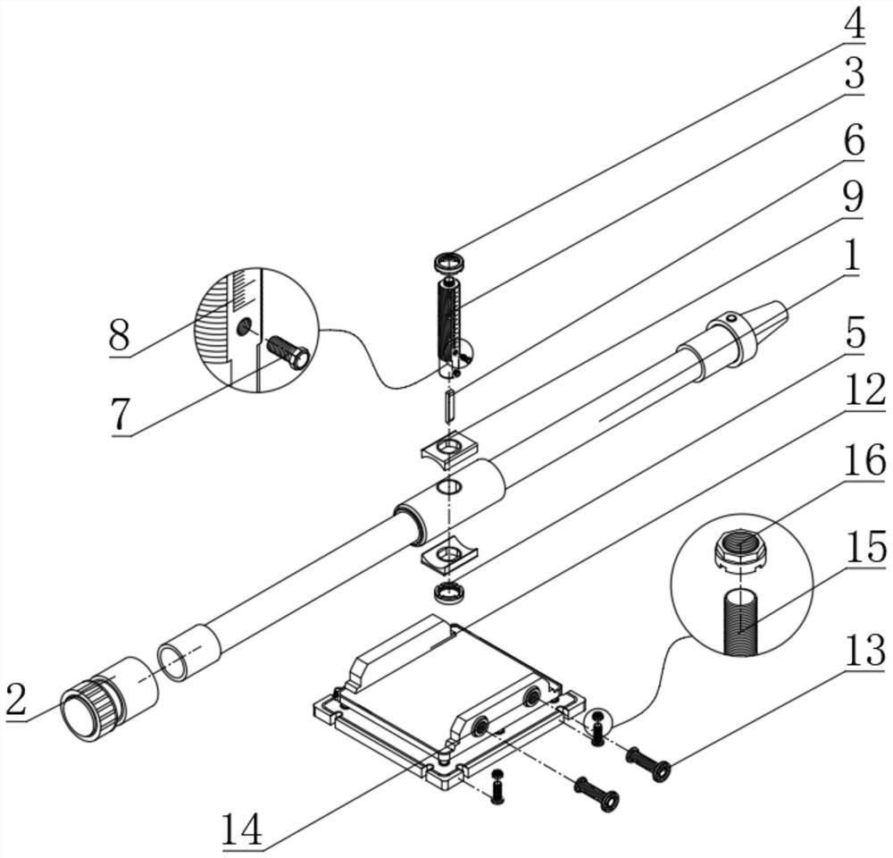
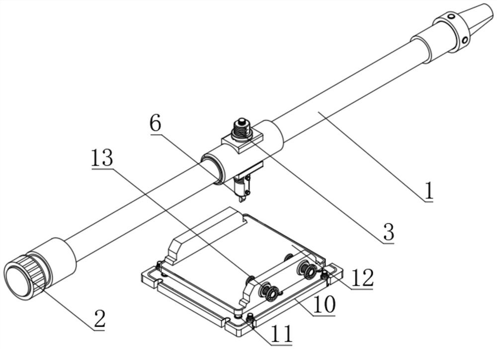
[0042] see Figure 1-3 , a curved surface forming device for a precision forging hammer head tooling, characterized in that it includes a mounting frame, a cutting mechanism, an adjusting mechanism and a clamping mechanism, the adjusting mechanisms are all arranged on the mounting frame, the cutting mechanism is arranged on the adjusting mechanism, and the clamping mechanism The mechanism is connected to the cutting platform of the boring machine through a detachable mechanism, wherein: the mounting frame includes a boring bar 1 and a movable sleeve 2, and the inside of the movable sleeve 2 is sleeved on one end of the boring bar 1 through a card slot opened, and the movable sleeve 2 and the connection between the boring bar 1, the boring bar 1 can be rotated inside the movable sleeve 2;
[0043] In this embodiment, as an alternative, one end of the boring bar 1 can be fixedly connected with a groove block with a diameter larger than the movable sleeve 2, and the inside of the...
Embodiment 2
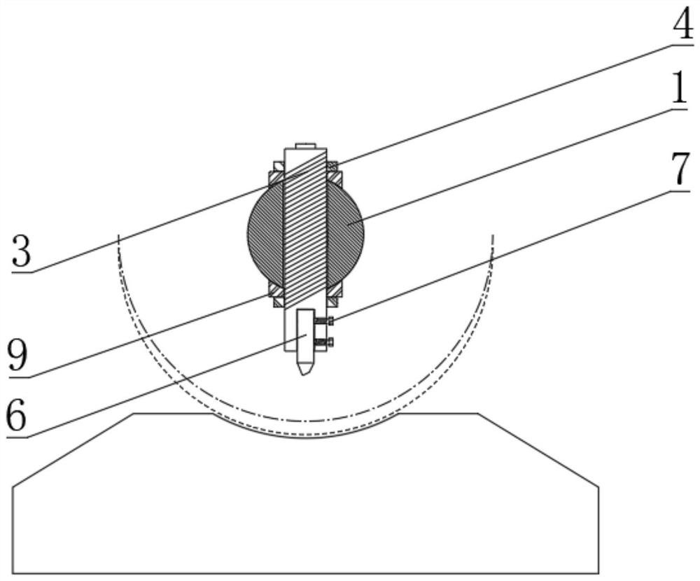
[0047] According to Embodiment 1, the surface of the installation shaft 3 is screwed to the limit bolt 7 through the threaded hole provided, and one end of the limit bolt 7 penetrates the installation shaft 3 to contact the surface of the boring tool 6, and the surface of the installation shaft 3 is provided with a scale Line 8, through the connection between the limit bolt 7 and the installation shaft 3, the limit bolt 7 can rotate and move inside the installation shaft 3, and through the action of the limit bolt 7, the distance between the boring tool 6 and the installation shaft 3 can be adjusted. The connection between the positions is limited. Through the function of the scale line 8, the length adjusted by the installation axis 3 can be more clearly defined.
[0048] In this embodiment, as a preferred solution, the scale mark 8 can be replaced with the length of a suitable unit of measurement according to the needs of the staff, such as millimeters or centimeters, so that...
Embodiment 3
[0051] According to Embodiment 1, the surface of the installation shaft 3 is contacted with pads 9, and the number of pads 9 is two. The two pads 9 are arranged symmetrically with the center line of the installation shaft 3 as the axis of symmetry. The upper stop ring 4 The bottom and the top of the lower active ring 5 are connected to the pad 9 respectively, through the connection between the pad 9 and the installation shaft 3, the pad 9 can be installed or disassembled, and through the connection between the pad 9 and the upper stop ring 4 The connection between them can improve the tightness of the upper stop ring 4, reduce the chance of the upper stop ring 4 being skewed, and improve the stability;
[0052] In this embodiment, as an alternative, a threaded hole can be provided on the surface of the spacer 9, and a threaded hole of the same size can be provided at the corresponding position of the installation shaft 3, and the bolts can be used to connect the spacer between ...
PUM
 Abstract
Description
Claims
Application Information
 - R&D Engineer
- R&D Manager
- IP Professional
- Industry Leading Data Capabilities
- Powerful AI technology
- Patent DNA Extraction
Browse by: Latest US Patents, China's latest patents, Technical Efficacy Thesaurus, Application Domain, Technology Topic, Popular Technical Reports.
© 2024 PatSnap. All rights reserved.Legal|Privacy policy|Modern Slavery Act Transparency Statement|Sitemap|About US| Contact US: help@patsnap.com


