Welding circle cutting device
A technology of movable connection and assembly, which is applied in welding equipment, laser welding equipment, metal processing equipment, etc., can solve the problems of time-consuming and laborious adjustment of cutting radius, and it is not conducive to the flexible operation and adjustment of staff, and achieves the effect of convenient and flexible operation and use.
- Summary
- Abstract
- Description
- Claims
- Application Information
AI Technical Summary
Problems solved by technology
Method used
Image
Examples
Embodiment 1
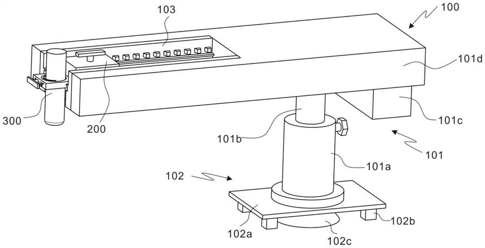
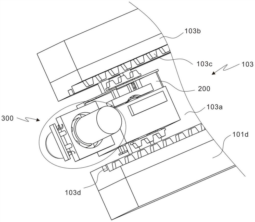
[0033] refer to figure 1 , 2 and 4, is the first embodiment of the present invention, this embodiment provides a welding circle cutting device, including a rotating module 100, the rotating module 100 includes a rotating component 101, an adsorption component 102 and a sliding engagement component 103, the rotating components 101 are respectively It is movably connected with the suction assembly 102 and the sliding engagement assembly 103 .
[0034] When using the equipment to cut a circle on the plate, the user places the whole device on the surface of the plate, connects the plate with the adsorption component 102 to fix the device, and then manually rotates the rotating component 101 to realize the manual displacement module 200 and the plate. The driving of the cutting assembly 300 causes the two to rotate, and the bottom of the device is stably connected to the plate, so that the rotation trajectory of the manual displacement module 200 and the cutting assembly 300 is ci...
Embodiment 2
[0039] refer to figure 1 as well as Figures 4 to 7 , is the second embodiment of the present invention, which is based on the previous embodiment.
[0040] The rotating assembly 101 includes a movable rod 101a, an adjustment rod 101b, a counterweight 101c and a rotating plate 101d. One end of the adjustment rod 101b penetrates into the inner cavity of the movable rod 101a, the outer wall of the movable rod 101a is threadedly connected with a locking bolt, and the adjustment rod 101b The other end is fixedly connected to the rotating plate 101d, and one end of the counterweight 101c is connected to the rotating plate 101d. With the adjusting rod 101b as the fulcrum, the two ends of the rotating plate 101d are unbalanced. The force is balanced at both ends, and the manufacturing cost is reduced.
[0041] When the cutting height of the equipment needs to be adjusted, the user can remove the locking bolts on the outer wall of the movable rod 101a, and the staff can manually adj...
Embodiment 3
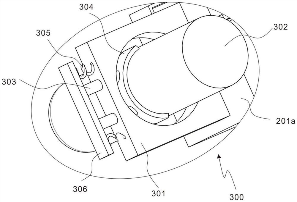
[0052] refer to Figures 2 to 3 as well as Figures 5 to 10 , is the second embodiment of the present invention, which is based on the previous embodiment.
[0053] After the cutting radius of the laser cutting equipment is adjusted, the equipment needs to be fixed to ensure stable rotating cutting.
[0054] The locking drive assembly 202 includes a sleeve rod 202a, a drive rod 202b, a drive handle 202c and a torsion spring 202d. One end of the sleeve rod 202a is movably connected to the sliding housing 201a through a bearing, and one end of the drive rod 202b penetrates into the sleeve rod 202a to drive The other end of the rod 202b penetrates the sliding housing 201a and is connected with the driving handle 202c. The torsion spring 202d is sleeved on the outer wall of the driving rod 202b, and the two ends of the torsion spring 202d are respectively connected with the outer wall of the driving rod 202b and the inner wall of the sliding housing 201a. .
[0055] When lockin...
PUM
 Abstract
Description
Claims
Application Information
 - R&D Engineer
- R&D Manager
- IP Professional
- Industry Leading Data Capabilities
- Powerful AI technology
- Patent DNA Extraction
Browse by: Latest US Patents, China's latest patents, Technical Efficacy Thesaurus, Application Domain, Technology Topic, Popular Technical Reports.
© 2024 PatSnap. All rights reserved.Legal|Privacy policy|Modern Slavery Act Transparency Statement|Sitemap|About US| Contact US: help@patsnap.com


