Glass cutting robot
A technology of glass cutting and robotics, applied in the field of robotics, can solve problems such as heavy workload and unsafety, and achieve the effect of improving practicability, convenient adjustment, and flexible adjustment of cutting radius
- Summary
- Abstract
- Description
- Claims
- Application Information
AI Technical Summary
Problems solved by technology
Method used
Image
Examples
Embodiment 1
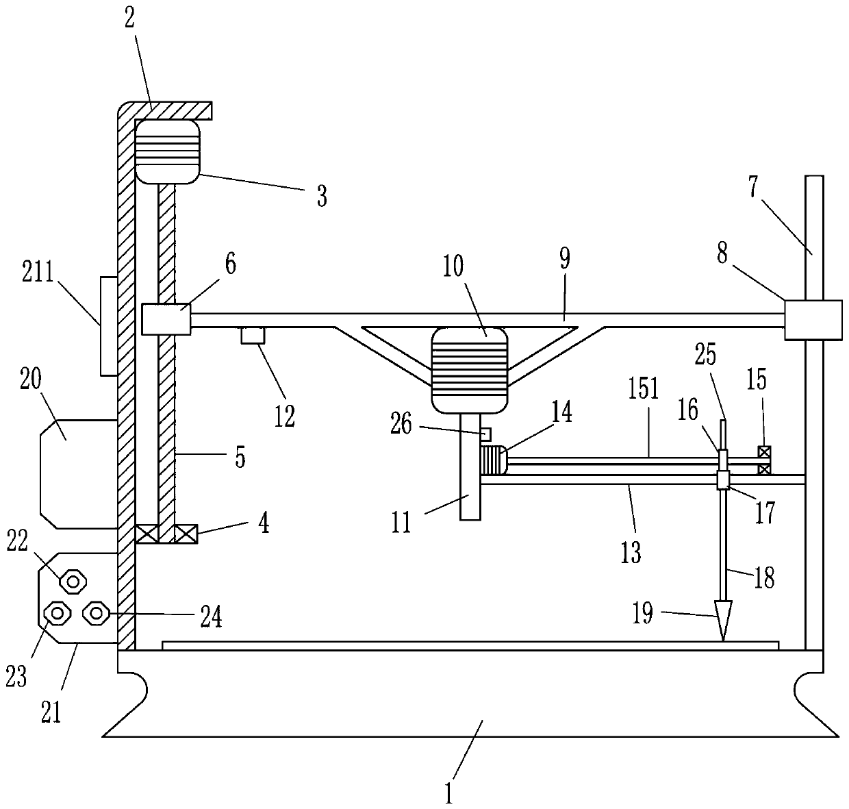
[0018] A glass cutting robot such as Figure 1-4 As shown, it includes cutting seat 1, mounting plate 2, upper servo motor 3, lower bearing seat 4, vertical screw rod 5, vertical nut 6, guide rail 7, guide sleeve 8, lifting plate 9, rotating motor 10, rotating Rod 11, first distance sensor 12, slide rail 13, lower servo motor 14, right bearing seat 15, transverse screw rod 151, transverse nut 16, slider 17, connecting rod 18, cutting knife 19, control box 20, fixed plate 21. Control panel 211, execution switch 22, height lift switch 23, lateral movement switch 24, moving block 25 and second distance sensor 26, the top left side of cutting seat 1 is connected with mounting plate 2, and the top of mounting plate 2 is installed with On the servo motor 3, the lower bearing seat 4 is installed on the lower side of the right wall of the mounting plate 2, and a vertical screw rod 5 is connected between the upper servo motor 3 and the lower bearing seat 4, and a vertical screw rod 5 i...
Embodiment 2
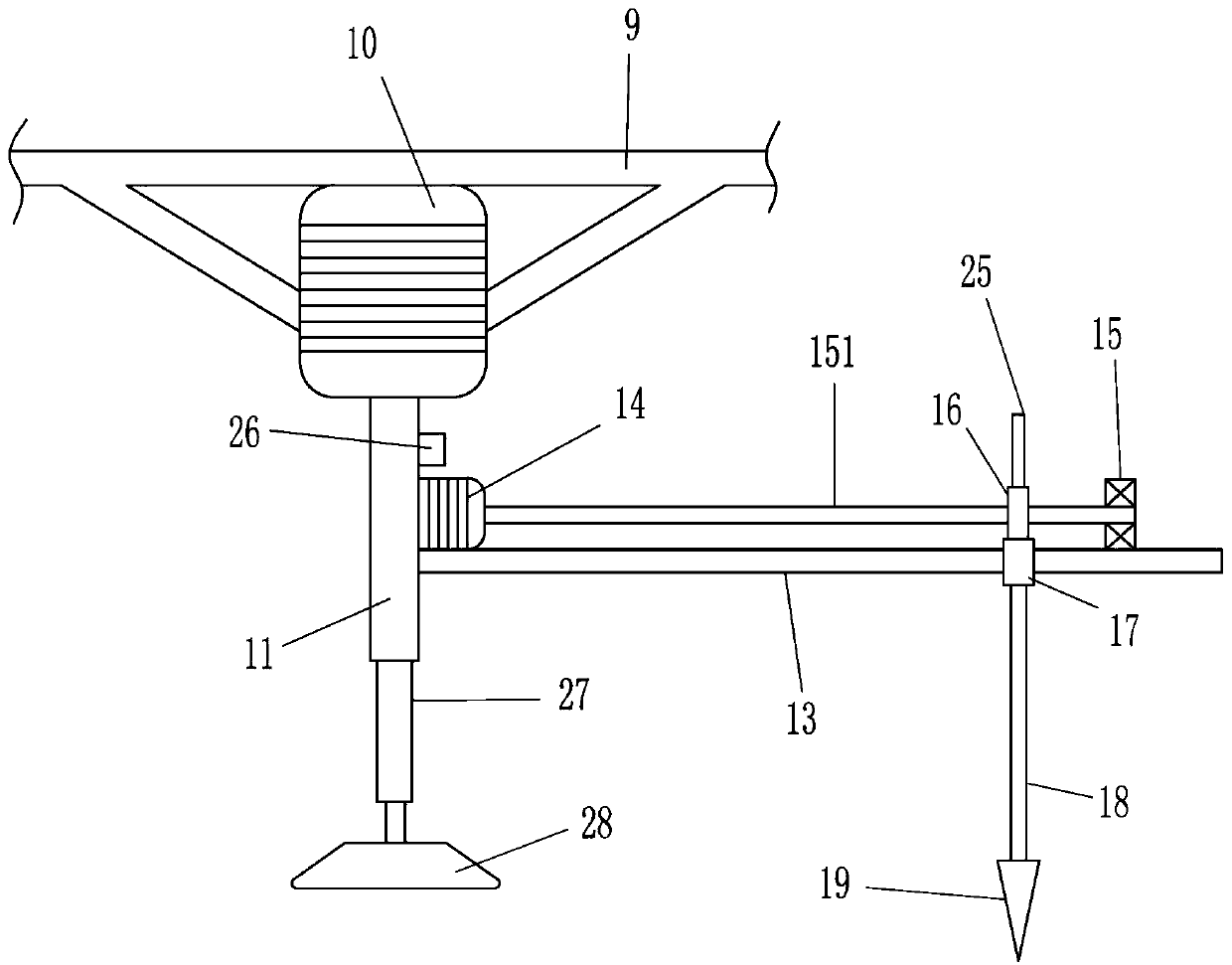
[0020] A glass cutting robot such as Figure 1-4As shown, it includes cutting seat 1, mounting plate 2, upper servo motor 3, lower bearing seat 4, vertical screw rod 5, vertical nut 6, guide rail 7, guide sleeve 8, lifting plate 9, rotating motor 10, rotating Rod 11, first distance sensor 12, slide rail 13, lower servo motor 14, right bearing seat 15, transverse screw rod 151, transverse nut 16, slider 17, connecting rod 18, cutting knife 19, control box 20, fixed plate 21. Control panel 211, execution switch 22, height lift switch 23, lateral movement switch 24, moving block 25 and second distance sensor 26, the top left side of cutting seat 1 is connected with mounting plate 2, and the top of mounting plate 2 is installed with On the servo motor 3, the lower bearing seat 4 is installed on the lower side of the right wall of the mounting plate 2, and a vertical screw rod 5 is connected between the upper servo motor 3 and the lower bearing seat 4, and a vertical screw rod 5 is...
Embodiment 3
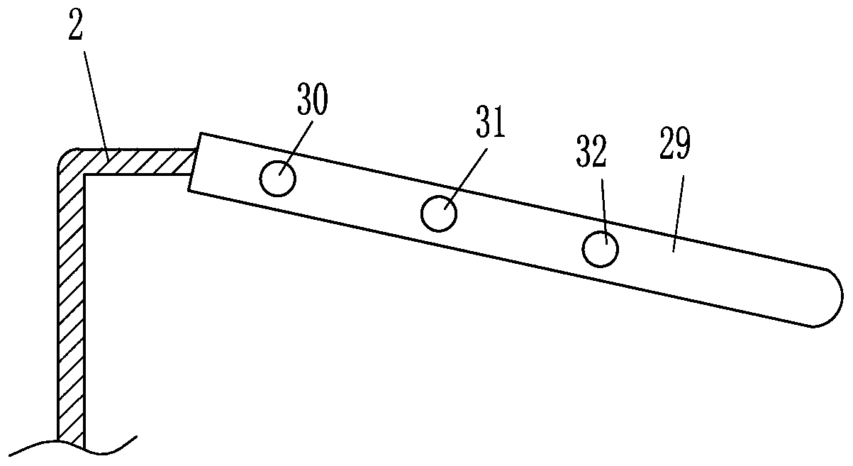
[0023] A glass cutting robot such as Figure 1-4 As shown, it includes cutting seat 1, mounting plate 2, upper servo motor 3, lower bearing seat 4, vertical screw rod 5, vertical nut 6, guide rail 7, guide sleeve 8, lifting plate 9, rotating motor 10, rotating Rod 11, first distance sensor 12, slide rail 13, lower servo motor 14, right bearing seat 15, transverse screw rod 151, transverse nut 16, slider 17, connecting rod 18, cutting knife 19, control box 20, fixed plate 21. Control panel 211, execution switch 22, height lift switch 23, lateral movement switch 24, moving block 25 and second distance sensor 26, the top left side of cutting seat 1 is connected with mounting plate 2, and the top of mounting plate 2 is installed with On the servo motor 3, the lower bearing seat 4 is installed on the lower side of the right wall of the mounting plate 2, and a vertical screw rod 5 is connected between the upper servo motor 3 and the lower bearing seat 4, and a vertical screw rod 5 i...
PUM
 Abstract
Description
Claims
Application Information
 - R&D Engineer
- R&D Manager
- IP Professional
- Industry Leading Data Capabilities
- Powerful AI technology
- Patent DNA Extraction
Browse by: Latest US Patents, China's latest patents, Technical Efficacy Thesaurus, Application Domain, Technology Topic, Popular Technical Reports.
© 2024 PatSnap. All rights reserved.Legal|Privacy policy|Modern Slavery Act Transparency Statement|Sitemap|About US| Contact US: help@patsnap.com


