
Large-flow plug-in type electro-hydraulic servo valve with valve element combined with horizontal rotation

An electro-hydraulic servo valve, large flow technology, applied in the field of hydraulic valves, can solve the problems of weak oil pollution resistance, reduced system reliability, complex hydraulic system, etc., to improve control accuracy and response speed, structural design optimization, The effect of strong anti-pollution ability

Pending Publication Date: 2022-03-22
油威力液压科技股份有限公司
View PDF0 Cites 0 Cited by
  • Summary
  • Abstract
  • Description
  • Claims
  • Application Information

AI Technical Summary

Problems solved by technology

[0003] In the prior art, the plug-in electro-hydraulic servo valve can solve the problem of insufficient driving force by controlling the movement of the pilot stage and then controlling the movement of the main spool through the flow amplification stage, but due to the multi-stage structure, the valve as a whole will become More complex, resulting in weaker oil pollution resistance, lower system reliability and higher cost, limiting its application
In addition, adding a pilot valve makes the hydraulic system must provide a pilot oil circuit, which will cause the entire hydraulic system to become complicated

Method used


Image

  • Large-flow plug-in type electro-hydraulic servo valve with valve element combined with horizontal rotation
  • Large-flow plug-in type electro-hydraulic servo valve with valve element combined with horizontal rotation
  • Large-flow plug-in type electro-hydraulic servo valve with valve element combined with horizontal rotation

Examples


Embodiment Construction

[0041] The present invention will be described in further detail below in conjunction with the accompanying drawings and embodiments. It should be understood that the specific embodiments described here are only used to explain the present invention, not to limit the present invention.

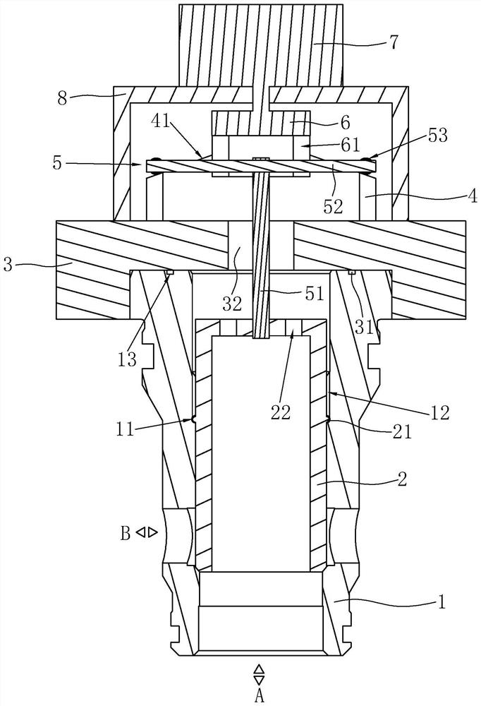
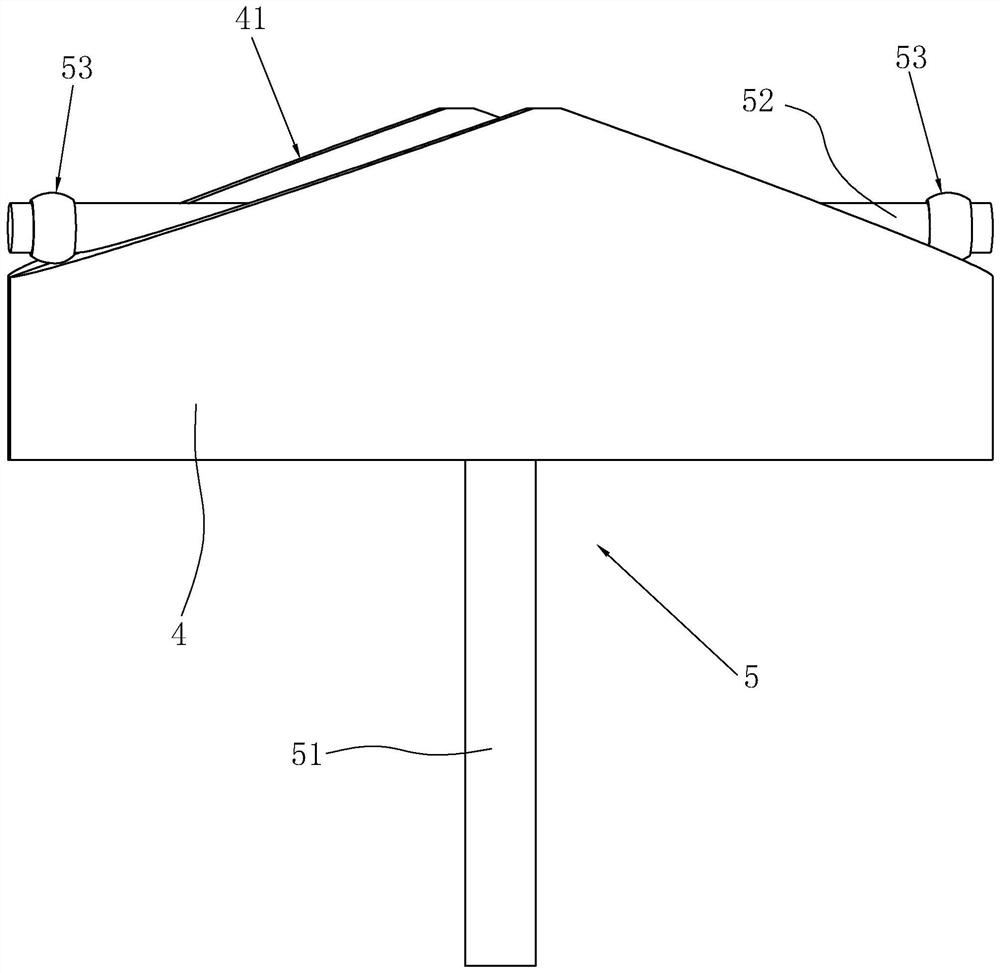
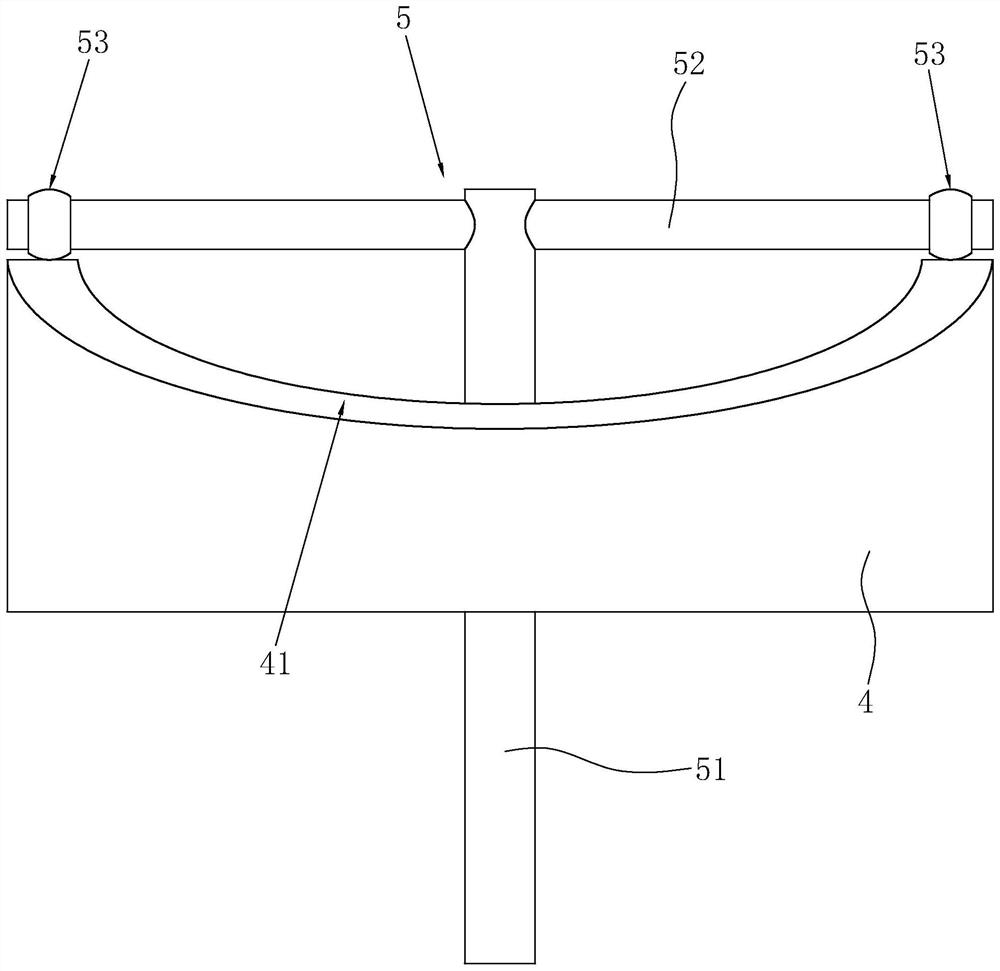
[0042] A large-flow plug-in electro-hydraulic servo valve combined with horizontal rotation of the spool, such as figure 1 As shown, including the main valve sleeve 1, the main valve core 2, and the cover plate 3, an oil inlet A is provided at the lower end of the main valve sleeve 1, and a circular array is provided on the outer wall of the main valve sleeve 1 near the bottom. Oil outlet B is formed, the main valve core 2 slides vertically and is rotatably installed in the main valve sleeve 1, and the oil outlet B is opened or closed by the vertical sliding of the main valve core 2. The main spool 2 is a hollow structure with an opening at the bottom, and its bottom opening communicates with...


PUM


Abstract

The invention provides a large-flow plug-in type electro-hydraulic servo valve with a valve element combined with horizontal rotation, and relates to the technical field of hydraulic valves, the large-flow plug-in type electro-hydraulic servo valve comprises a main valve sleeve, a main valve element and a cover plate, an oil inlet A and an oil outlet B are formed in the main valve sleeve, the cover plate covers the top of the main valve sleeve, and the main valve element vertically slides and is rotatably installed in the main valve sleeve; the main valve element is connected with a horizontal rotation combination mechanism. The horizontal rotation combination mechanism comprises a horizontal rotation rail, a T-shaped guide rod, a torsion device and a stepping motor. The horizontal rotating track is fixed on the upper end surface of the cover plate, and the upper end surface is a circular track surface; the T-shaped guide rod comprises a vertical lifting rod and a horizontal clamping rod. The lower end of the vertical lifting rod is fixedly connected with the upper end of the main valve element. The upper end face of the twisting device is fixedly connected with the stepping motor, vertically-arranged limiting grooves are symmetrically formed in the lower end face of the twisting device, the two ends of the horizontal clamping rod are clamped and vertically installed in the limiting grooves in a sliding mode, and pulleys rolling on the horizontal rotating rails are arranged at the two ends of the horizontal clamping rod. The invention has the characteristics of high sensitivity, high reliability, small volume, pollution resistance, large flow and the like.

Description

technical field [0001] The invention relates to the technical field of hydraulic valves, in particular to a large-flow plug-in electro-hydraulic servo valve with a valve core combined with horizontal rotation. Background technique [0002] As one of the important components of the hydraulic system, the plug-in electro-hydraulic servo valve is frequently used in the hydraulic system, and its working control accuracy also affects the control accuracy of the entire hydraulic system. The plug-in electro-hydraulic servo valve in the prior art is usually composed of main valve core, valve sleeve, pilot valve, displacement sensor, integrated control circuit and other components. There are two pilot control chambers on the main valve core, and the pilot valve controls the pilot valve. Cavity pressure, and then control the displacement of the main spool, the main spool is fed back through the high-pressure displacement sensor to form a closed-loop control of the displacement of the m...

Claims


Application Information

Patent Timeline
Patent Type & Authority Applications(China)
IPC IPC(8): F16K1/00F16K1/38F16K27/02F16K31/524F16K31/04F16K27/08F15B13/02
CPCF16K1/00F16K1/38F16K27/0254F16K31/5245F16K31/52441F16K31/047F16K27/08F15B13/02
Inventor 陈逸嘉王生安陈博赵静一张浩
Owner 油威力液压科技股份有限公司
Learn More