Leveling device for linear drainage ditch of bridge

A technology for leveling devices and drainage ditches, applied in bridges, bridge parts, bridge construction, etc., can solve problems such as difficulty in keeping the slope of the bridge deck consistent, non-adjustable, fixed height, etc., achieve structural stability, increase service life, and facilitate adjustment Effect

Pending Publication Date: 2022-03-22
CCCC FIRST HIGHWAY XIAMEN ENG +1
View PDF0 Cites 0 Cited by
  • Summary
  • Abstract
  • Description
  • Claims
  • Application Information

AI Technical Summary

Problems solved by technology

[0004] However, the linear drainage ditch, which combines many advantages, encountered a serious problem during construction: the height of the linear drainage ditch itself is fixed and cannot be adjusted, and the slope after installation is consistent with the slope of the ditch bottom. It is difficult to keep consistent, and the depth is also difficult to control with the slope, so a bridge linear drainage ditch leveling device is urgently needed to meet the stringent requirements of the drainage ditch closing surface

Method used


Image

  • Leveling device for linear drainage ditch of bridge
  • Leveling device for linear drainage ditch of bridge
  • Leveling device for linear drainage ditch of bridge

Examples


Embodiment 1

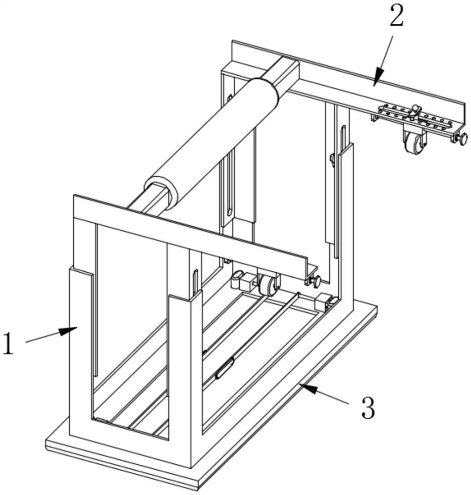
[0055] Such as Figure 1-9 As shown, a bridge linear drain leveling device according to an embodiment of the present invention includes a connecting mechanism 1, a guiding mechanism 2 installed on the top of the connecting mechanism 1, and a smoothing mechanism 3 installed on the bottom of the connecting mechanism 1 ;

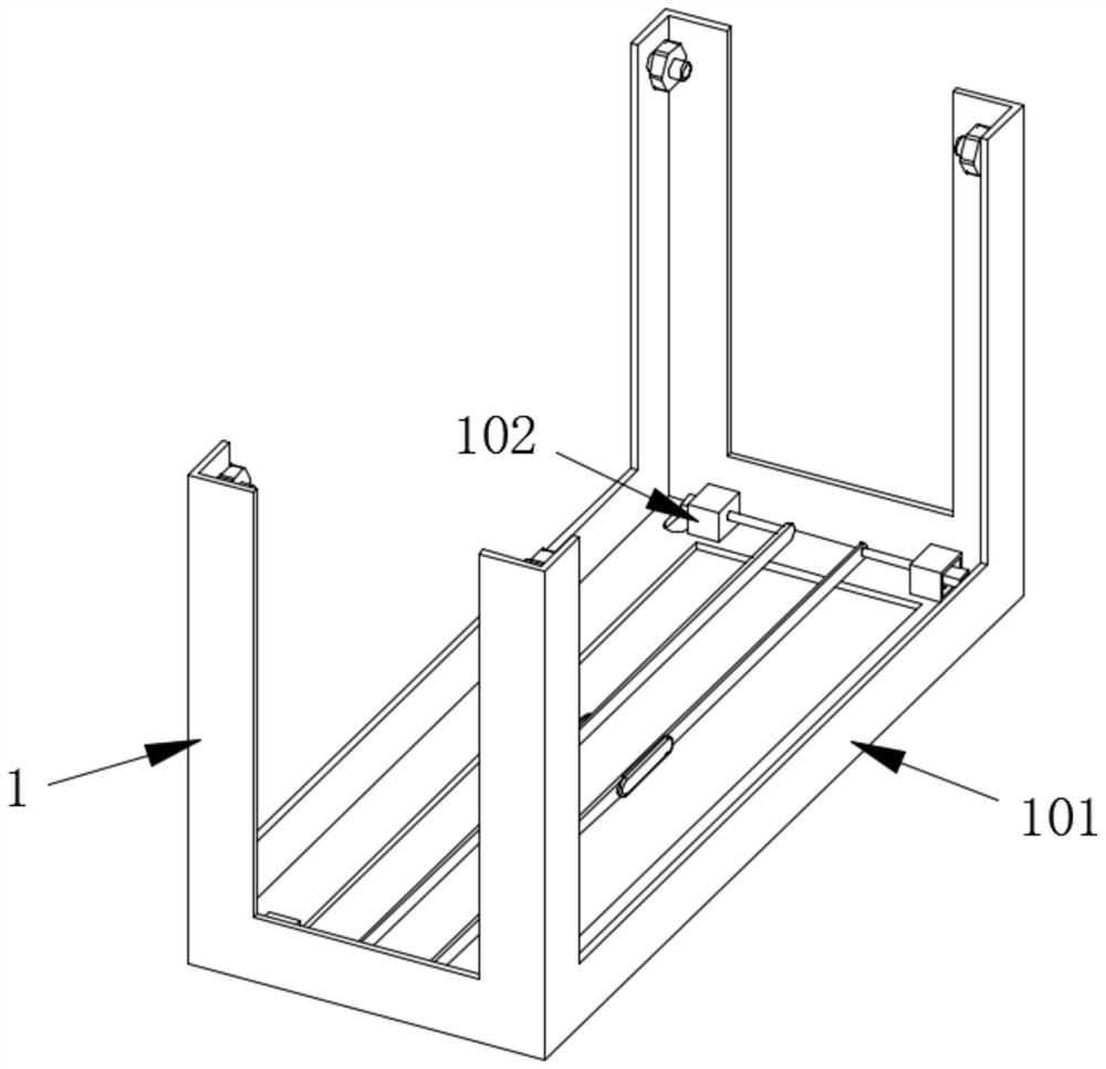
[0056] Wherein, the connection mechanism 1 is composed of a connection component 101 and two clamping components 102 symmetrically installed on the connection component 101;

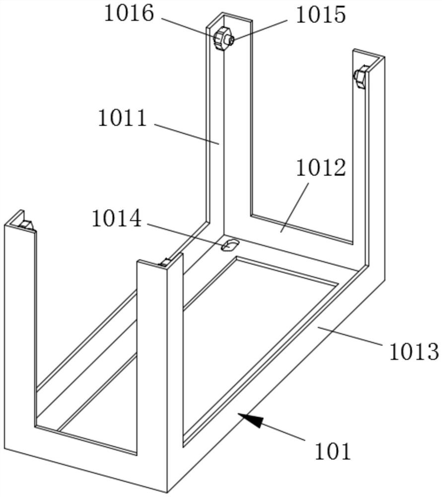
[0057] Wherein, the connection assembly 101 includes four vertical angle steels 1011, and the two vertical angle steels 1011 on the same side are fixedly connected by a transverse angle steel 1012, and the two horizontal angle steels 1012 are fixedly connected with symmetrically arranged The two longitudinal angle steels 1013 are provided with two symmetrically arranged mounting holes 1014 on the two longitudinal angle steels 1013, and the sides of the vertical angle steels 1011 are fixe...

Embodiment 2

[0071] Such as Figure 1-9 As shown, the difference between this embodiment and Embodiment 1 is that a positioning assembly 2058 is installed on the top of the threaded sleeve 2054, and the positioning assembly 2058 includes a cylinder 20581 fixedly connected to the top of the threaded sleeve 2054, The bottom of the inner wall of the cylinder 20581 is fixedly connected with a positioning spring 20582, and the top of the positioning spring 20582 is fixedly connected with a cylinder 20583 slidingly connected with the cylinder 20581, and the top of the cylinder 20583 moves through the cylinder The body 20581 is set and extended to the top of the barrel 20581 and is fixedly connected with a mounting rod 20584 , and both sides of the bottom of the mounting rod 20584 are fixedly connected with a limit rod 20585 matching with the limit groove 207 .

[0072] By adopting the above technical solution, the adjusted guide wheel 2057 can be limited and fixed, thereby improving the stabilit...

Embodiment 3

[0074] Such as Figure 1-9 As shown, the difference between this embodiment and Embodiment 2 is that the positioning assembly 2058 also includes a pull handle 205841 fixedly connected to the top of the installation rod 20584, and the limit rod 20585 is set in an arc shape, so The sides of the block 10215 are set in an arc shape.

[0075] By adopting the above technical solution, it is not only convenient to pull the installation rod 20584, but also increases the convenience of the stop rod 20585 snapping into the stop slot 207, and improves the convenience of snapping the block 10215 into the slot 303.


PUM


Abstract

The invention discloses a leveling device for a linear drainage ditch of a bridge. The leveling device comprises a connecting mechanism, a guide mechanism mounted at the top of the connecting mechanism and a trowelling mechanism mounted at the bottom of the connecting mechanism. According to the device, the height and the gradient of the whole device are determined along with a paved asphalt pavement, high maneuverability is achieved, a user only needs to hold a handle with hands and push the device back and forth to finish surface finishing, and the stooping frequency is reduced; the trowelling depth and the width from the slope can be adjusted according to the actual requirements of the drainage ditch, so that the applicability of the device is improved; the trowel made of an aluminum plate has a good anti-corrosion function, so that the service life of the device is prolonged, and the trowel is convenient to disassemble and assemble, so that when the trowel is damaged, the trowel is convenient to replace, and the practicability is improved; the whole device adopts an angle steel framework, is stable in structure, and is convenient to use and carry, so that the working efficiency is practically and effectively improved.

Description

technical field [0001] The invention relates to the technical field of drainage ditch leveling devices, in particular to a bridge linear drainage ditch leveling device. Background technique [0002] The linear drainage system is a straight line that is clean and tidy. In fact, the rationale is basically the same. The linear drainage system first originated in the European market. The linear drainage system is a modular system composed of a variety of components. The combination of modules of various specifications can meet the needs of various customers. Its unique design concept also creates more room for imagination and development for designers, and becomes a more reliable product in the field of modern architecture. [0003] The material of the drainage ditch is resin concrete, which is a new type of building material. Its components are taken from natural minerals, such as quartz sand crystals, sandstone foam, granite, etc., which are screened according to particle size...

Claims


Application Information

Patent Timeline
Patent Type & Authority Applications(China)
IPC IPC(8): E01D21/00E01D19/08
CPCE01D21/00E01D19/086
Inventor 卢国庆王金山王国友邢轩隋国瑞王海丽方鑫伟
Owner CCCC FIRST HIGHWAY XIAMEN ENG
Why Eureka
Try Eureka