Pattern splicing method for maskless laser high-precision scanning

A high-precision, mask-less technology, used in optics, optomechanical equipment, microlithography exposure equipment, etc. The effect of high performance, meeting the requirements of high precision and reducing distortion index

Pending Publication Date: 2022-03-18
锡凡半导体无锡有限公司
View PDF0 Cites 0 Cited by
  • Summary
  • Abstract
  • Description
  • Claims
  • Application Information

AI Technical Summary

Problems solved by technology

However, due to oblique scanning, splicing is inevitable between the front and back exposure areas of the image
In addition, due to the existence of lens distortion and other factors, the image in the stitching area will be shifted or blurred, which is difficult to meet the industrial needs of high precision and high resolution

Method used


Image

  • Pattern splicing method for maskless laser high-precision scanning
  • Pattern splicing method for maskless laser high-precision scanning
  • Pattern splicing method for maskless laser high-precision scanning

Examples


Embodiment Construction

[0019] The present invention will be further described below in conjunction with specific drawings and embodiments.

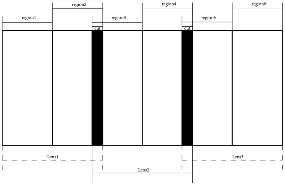
[0020] In order to effectively improve the splicing effect between exposure areas and meet the industrial needs of high precision and high resolution, the pattern splicing method for maskless laser high-precision scanning of the present invention specifically calibrates the DMD to Determine the angle and corresponding position of any lens corresponding to the DMD;

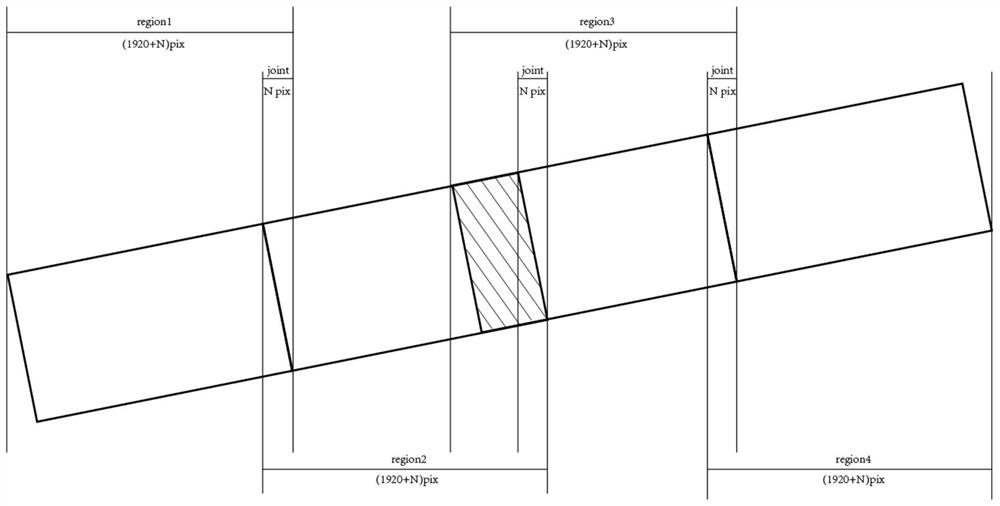
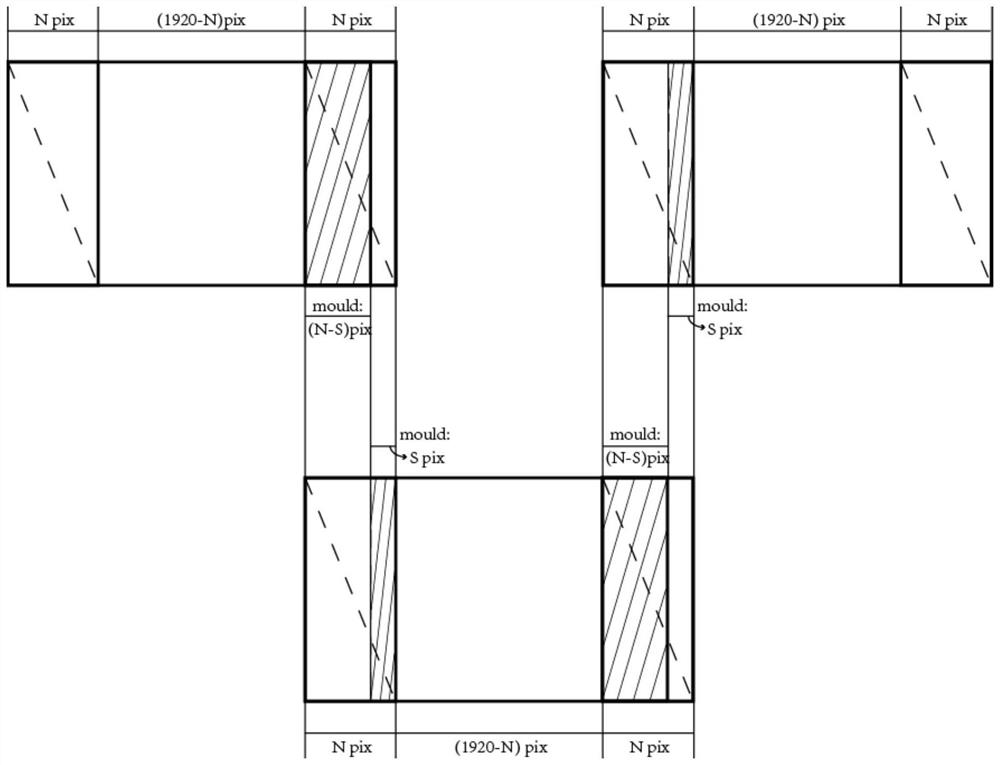
[0021] For any shot, determine the triangle stitching area in the shot formed by the lens projection according to the angle of the shot, and the triangle stitching area in the shot includes the positive exposure triangle stitching area formed in the positive exposure area and the triangle stitching area formed in the The anti-exposure triangle stitching area in the lens in the reverse exposure area, the positive exposure triangle stitching area in the lens and the reverse exposure triangle stitching...


PUM


Abstract

The invention relates to a pattern splicing method for maskless laser high-precision scanning. According to the method, the DMD is calibrated to determine the angle and the corresponding position of any lens corresponding to the DMD; when pattern splicing is carried out on a front exposure area and a back exposure area formed by projection of a lens, in-lens front exposure triangular splicing area exposure parameters of an in-lens front exposure triangular splicing area and in-lens back exposure triangular splicing area exposure parameters of an in-lens back exposure triangular splicing area are configured; the sum of the effective exposure times in the exposure parameters of the positive exposure triangular splicing area in the lens and the effective exposure times in the exposure parameters of the negative exposure triangular splicing area in the lens is k times of the number of pixels contained in the horizontal splicing length in the lens, and k ranges from 0.5 to 0.9. According to the invention, the splicing effect between the exposure areas can be effectively improved, the flexibility is high, and the industrial requirements of high precision and high resolution can be met.

Description

technical field [0001] The invention relates to a pattern splicing method, in particular to a pattern splicing method for maskless laser high-precision scanning. Background technique [0002] Maskless laser direct writing lithography uses the digital mask of digital micromirror device (DMD) instead of the physical mask of traditional lithography, which enhances the flexibility of lithography. At the same time, by tilting the DMD at a certain angle, in the vertical and horizontal directions, high-precision scanning of the DMD at the sub-pixel level is realized. [0003] The so-called sub-pixel is a unit smaller than a pixel, that is, several sub-pixels are combined to form a pixel. One DMD pixel corresponds to one pixel, and the DMD can be used to scan obliquely to display graphic data on the DMD with sub-pixel accuracy. However, due to oblique scanning, stitching inevitably occurs between the front and back exposure areas of the image. In addition, due to the existence of...

Claims


Application Information

Patent Timeline
IPC IPC(8): G03F7/20
CPCG03F7/2053G03F7/70358G03F7/704G03F7/70475
Inventor 霍大云杨琳韵茆荣超
Owner 锡凡半导体无锡有限公司
Why Eureka
Try Eureka