
Novel efficient solar heat collecting tube

A solar heat collecting tube, high-efficiency technology, applied in the field of solar heat collecting tubes, can solve the problems of high manufacturing cost, small heating area, high cost, etc., and achieve the effects of high cost, improved start-up speed, and high absorption rate

Pending Publication Date: 2022-03-18
江苏省埃迪机电设备实业有限公司
View PDF8 Cites 0 Cited by
  • Summary
  • Abstract
  • Description
  • Claims
  • Application Information

AI Technical Summary

Problems solved by technology

[0003] The solar collector tube mainly realizes heat collection through a number of vacuum collector tubes with vacuum walls, and the manufacturing cost is high. The heat absorption rate of the collector tube is a very important performance parameter. At present, there are steel tube structures, which can guarantee a certain strength and heat absorption. Good, but the cost is high, the heating area is small, and it must be used with a concentrator at high temperature, and there are still many practical problems. For this, this application proposes a new type of high-efficiency solar heat collecting tube

Method used


Image

  • Novel efficient solar heat collecting tube
  • Novel efficient solar heat collecting tube
  • Novel efficient solar heat collecting tube

Examples


Embodiment 1

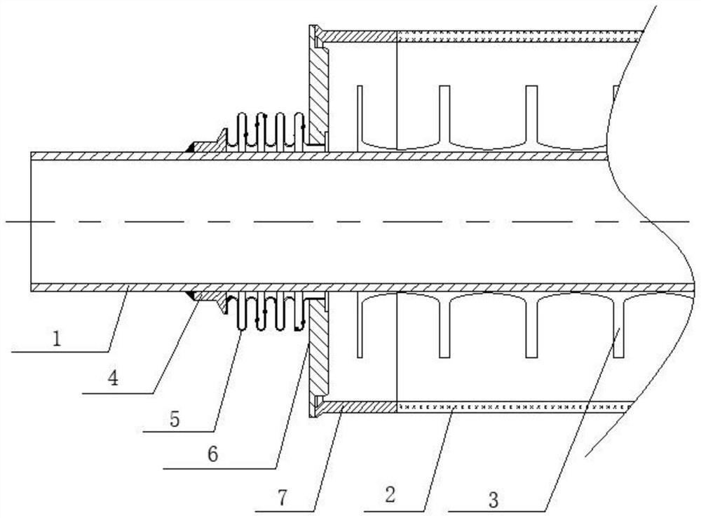
[0033] A new type of high-efficiency solar heat collection tube, including an inner stainless steel tube 1 and an outer glass tube 2 coaxially sleeved, the two ends of the inner stainless steel tube 1 and the outer glass tube 2 are sealed and connected by a seal, and the outer wall of the inner stainless steel tube 1 is provided with copper wings Flat plate 3, copper wing flat plate 3 is TU1 copper strip; wherein, the seal includes connecting pipe 4, expansion compensation bellows 5, kovar connector 6, and kovar 7.

[0034] The connecting pipe is fixedly connected with the expansion compensation bellows, and is welded to the outer wall of the inner stainless steel pipe at the end side of the connecting pipe. Dynamic balance, stronger application stability, wider temperature resistance and application temperature range, efficient and practical.

[0035] Among them, the thickness of the copper wing plate is 1% of the outer diameter of the inner stainless steel pipe, and the expa...

Embodiment 2

[0038] For the novel high-efficiency solar collector tube proposed in the embodiment, the preparation steps of the solar collector tube are as follows:

[0039] S1. Take the pre-treated stainless steel pipe and TU1 copper strip, press the TU1 thin strip tightly on the stainless steel pipe with a self-locking roller mold, and clean the coating, connect the two ends with connecting pipes and expansion compensation bellows, and The expansion compensation bellows has a built-in non-evaporable getter, and the inner stainless steel tube;

[0040] S2. Install the inner stainless steel tube in the outer glass tube through the kovar connector and kovar, and vacuumize the space between the inner stainless steel tube and the outer glass tube to form a vacuum cavity, that is, produce a high-vacuum solar heat collection tube.

[0041] Further, the outer glass tube has a double-layer structure, and the interlayer is evacuated to form a vacuum chamber.

[0042] Moreover, the wall surface in...


PUM

PropertyMeasurementUnit
thermal conductivityaaaaaaaaaa

Abstract

The novel efficient solar heat collecting tube comprises an inner stainless steel tube and an outer glass tube which are coaxially arranged in a sleeved mode, the two ends of the inner stainless steel tube and the two ends of the outer glass tube are connected in a sealed mode through sealing pieces, and a copper wing flat plate is arranged on the outer wall of the inner stainless steel tube and is a TU1 copper strip; according to the heat collection pipe, the pipe body structure is optimized, materials are reasonably selected and matched, the heat collection pipe has the excellent heat collection and heat conduction efficiency, the heat collection starting speed is high, the temperature range is 80-260 DEG C when light is condensed or not condensed, the application field is wide, the overall self-cleaning performance is good, and the effective service life is long; and the method is worthy of popularization and application.

Description

technical field [0001] The invention relates to the technical field of solar heat collecting tubes, in particular to a novel high-efficiency solar heat collecting tube. Background technique [0002] The heat collecting tube is the core of the solar water heater. Its structure is like an elongated thermos bile, with a vacuum between the inner and outer layers. The surface of the inner glass tube is coated with a spectrally selective absorption coating using a special process to absorb solar radiation energy to the maximum. After being irradiated by sunlight, photons hit the coating, and the solar energy is converted into heat energy. Water absorbs heat from the outside of the coating. This kind of solar water heater with mature technology and simple structure is widely used in many civil fields. [0003] The solar collector tube mainly realizes heat collection through a number of vacuum collector tubes with vacuum walls, and the manufacturing cost is high. The heat absorpti...

Claims


Application Information

Patent Timeline
Patent Type & Authority Applications(China)
IPC IPC(8): F24S10/40F24S70/30F24S80/30
CPCF24S10/40F24S70/30F24S80/30Y02E10/44
Inventor 李勇健李自强郭胜杰
Owner 江苏省埃迪机电设备实业有限公司
Learn More