
Ferrite blank sintering process

A ferrite and blank technology, applied in the field of materials, can solve the problems of large size, different upper and lower end faces, deformation of ferrite core blanks, etc., to achieve the effects of reducing deformation, increasing stacking height, and improving production efficiency

Inactive Publication Date: 2022-03-18
北京七星飞行电子有限公司
View PDF7 Cites 2 Cited by
  • Summary
  • Abstract
  • Description
  • Claims
  • Application Information

AI Technical Summary

Problems solved by technology

[0005] Therefore, the embodiment of the present invention provides a ferrite blank sintering process to solve the adhesion problem that occurs when the ferrite blanks are placed side by side or stacked together for high-temperature sintering in the existing sintering technology of soft ferrite; And the deformation problem after sintering of ferrite core blanks with large sizes, different upper and lower end faces, and no sealing, etc.

Method used


Image

  • Ferrite blank sintering process
  • Ferrite blank sintering process
  • Ferrite blank sintering process

Examples


Embodiment 1

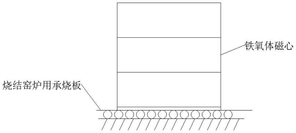
[0038] This embodiment provides a ferrite core blank sintering process, which specifically includes the following steps:

[0039] According to the predetermined placement position of multiple ferrite core blanks, use soft wool brush and other tools that will not damage the surface of ferrite core blanks, and according to the size and volume of ferrite core blanks, The contact surface of the oxygen body blank is coated with an appropriate amount of anti-adhesion coating; the anti-adhesion coating is a paste made by mixing and stirring water and corundum sand in a mass ratio of 2 to 3:1, and the particle size of the corundum sand is preferably ≤ 80 orders; What sintered in the present embodiment is the circular ferrite magnetic core;

[0040] After the multiple ferrite core blanks are coated and stacked in place, they are immediately sintered to avoid deformation of the ferrite core blanks due to moisture absorption due to excessive storage time. This embodiment adopts the form...

Embodiment 2

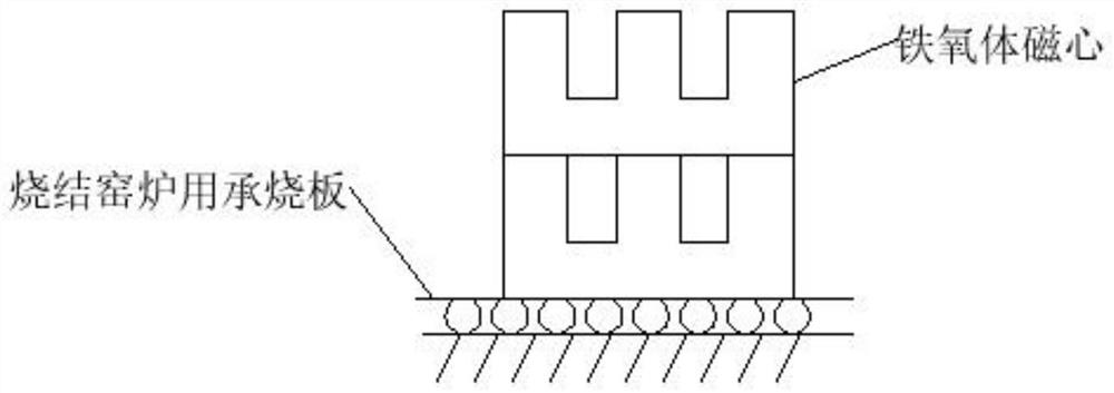
[0044] This embodiment provides a ferrite core blank sintering process, the operation steps of which are basically the same as those in Embodiment 1, the difference is that the ferrite core blanks in this embodiment are sintered by placing them side by side. Situation such as figure 2 shown. When sintering side by side, you also need to pay attention to the amount of coating. As mentioned above, too much will easily cause product deformation and cracking, and too little will not solve the problem of magnetic core adhesion and deformation; when placed side by side, the coating thickness is 0.8mm ~0.9mm is suitable, and 0.8mm is the best. The placement of the ferrite core blank in this embodiment is as follows figure 2 shown.

Embodiment 3

[0046] This embodiment provides a ferrite core blank sintering process, the operation steps of which are basically the same as those in Embodiment 1, the difference is that the E-type ferrite core blank is used in this embodiment. The placement of the E-type ferrite core blank in the present embodiment is as follows image 3 shown. The finished ferrite core obtained after sintering is as follows: Figure 5 shown.


PUM

PropertyMeasurementUnit
particle size (mesh)aaaaaaaaaa
thicknessaaaaaaaaaa
thicknessaaaaaaaaaa

Abstract

The invention discloses a ferrite blank sintering process which comprises the following steps: according to preset placement positions of a plurality of ferrite blanks, coating contact surfaces of adjacent ferrite blanks with an anti-adhesion coating; the anti-adhesion coating is prepared by mixing and stirring water and emery according to the mass ratio of (2-3): 1; and after a plurality of ferrite blanks are coated and stacked in place, sintering is carried out. The invention further discloses an anti-adhesion coating and application of the anti-adhesion coating in ferrite blank sintering pretreatment. The anti-adhesion coating is prepared by mixing and stirring water and emery according to the mass ratio of (2-3): 1. According to the ferrite blank sintering process disclosed by the invention, the adhesion problem occurring when the ferrite blanks are placed side by side or stacked together for high-temperature sintering can be solved; the ferrite magnetic core blank is large in size specification, different in upper end face and lower end face and not sealed after being sintered.

Description

technical field [0001] The invention relates to the field of materials, in particular to a ferrite blank sintering process. Background technique [0002] Sintering is a key process in the production of soft ferrite, the purpose is to solidify the ferrite powder that has been formed into one by pressing into a whole, so as to achieve the required electrical, magnetic and mechanical physical properties. The sintering process of ferrite is extremely complicated. At high temperature, in addition to the replacement and price change between ionic bonds, it is also accompanied by the shrinkage and densification process of the blank. [0003] The ferrite blank is formed by pressing the ferrite powder mixed with the binder together. When the blank is sintered at high temperature, it will experience a series of physical changes such as water evaporation, binder volatilization, liquid phase initiation, and solid phase reaction, which will cause adjacent ferrite parts that are stacked ...

Claims


Application Information

Patent Timeline
Patent Type & Authority Applications(China)
IPC IPC(8): C04B35/64C04B35/26
CPCC04B35/64C04B35/26
Inventor 孙瑞昕李想吕海波高喜英张小征张静刘娜段言辉王竹超
Owner 北京七星飞行电子有限公司
Learn More