
Rapid falling-off equipment for concrete cushion layer

A concrete cushion, fast technology, applied in the direction of stone processing equipment, work accessories, stone processing tools, etc., can solve the problems of difficult to remove the cushion, complicated operation, uneven removal, etc., to avoid dust everywhere and increase the breakdown depth. , the effect of improving the shedding effect

Pending Publication Date: 2022-03-18
中电建路桥集团有限公司
View PDF1 Cites 0 Cited by
  • Summary
  • Abstract
  • Description
  • Claims
  • Application Information

AI Technical Summary

Problems solved by technology

[0005] In order to overcome the disadvantages of the above-mentioned asphalt construction method in the construction process, such as complex operation, difficulty in removing the cushion and uneven removal, the technical problem to be solved is: to provide a quick fall-off equipment for the concrete cushion that is easy to operate and evenly falls off

Method used


Image

  • Rapid falling-off equipment for concrete cushion layer
  • Rapid falling-off equipment for concrete cushion layer
  • Rapid falling-off equipment for concrete cushion layer

Examples


Embodiment 1

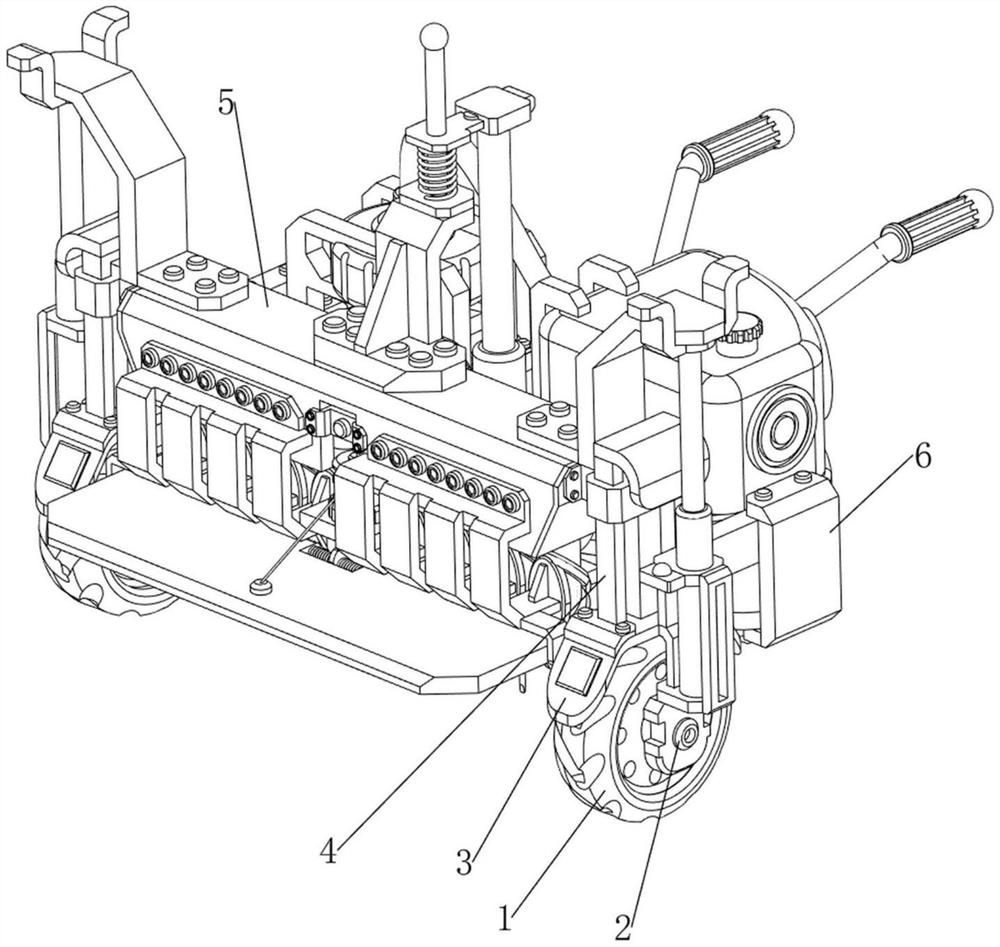
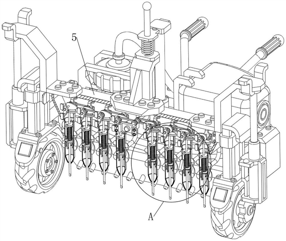
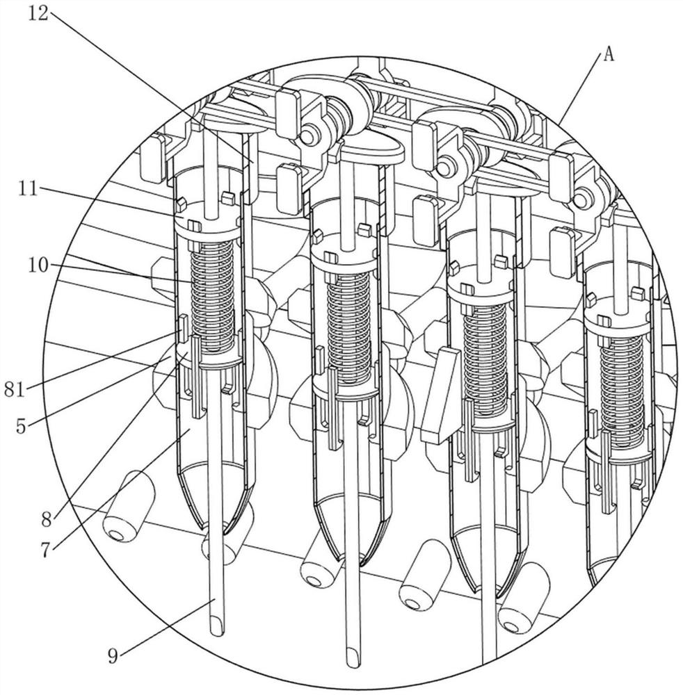
[0023] A fast shedding equipment of a concrete mat, such as Figure 1-6 As shown, including the front wheel 1, the first rotating shaft 2, the first support frame 3, the guide frame 4, the first fixing frame 5, the bottom frame 6, the casing 7, the slider 8, the guide block 81, the top rod 9, The first spring 10, the limit block 11, the slider 12, the connecting frame 13, the second rotating shaft 14, the control box 15, the contact switch 16, the rear wheel 141, the elevator 17, the vibration mechanism 18, extrusion mechanism 19 and the mobile mechanism 20, the bottom of the chassis 6 is provided with an armrest, and the bottom frame is provided with a guide frame 4 in front of the front portion, and the sliding frame is slidably equipped between the two guide frames 4, and the guide frame 4 is provided. There is a first support frame 3, and the lower portion of the first support frame 3 is provided with a first rotating shaft 2 by a bearing, and a front wheel 1 is provided on the...

Embodiment 2

[0030] On the basis of Example 1, such as Figure 5 , Figure 14 and Figure 15As shown, it includes a protective mechanism 21, and the protective mechanism 21 includes a third support frame 211, a baffle 212, a fourth support frame 213, a second deceleration motor 214, a fifth axis 215, a winding wheel 216, a drawn wire 217. , The sixth axis 218 and the torsion spring 219, the lower portion of the lower portion of the first fixing frame 5 is provided with the third support frame 211, and the first fixing frame 5 is fixed in the middle of the front side of the lower portion, and the fourth support frame 213, the fourth support frame are fixed. At the top of the 213, a second reduction motor 214 is attached, and the output shaft of the second reduction motor 214 is provided with a fifth axis 215 through a coupling. The upper portion of the fifth axis 215 is welded with winding wheel 216, the fourth support frame 213 lower portion and two A sixth axis 218 is connected between the third...


PUM


Abstract

The invention relates to concrete cushion falling-off equipment, in particular to rapid concrete cushion falling-off equipment. The invention provides the rapid falling-off equipment for the concrete cushion layer, which is simple to operate and can uniformly fall off. The rapid falling-off equipment for the concrete cushion comprises a bottom frame, a guide frame, a first fixing frame, a front wheel, a pile casing, a limiting block, an ejector rod and the like. Guide frames are arranged on the left side and the right side of the front portion of the bottom frame, a first fixing frame is arranged between the two guide frames in a sliding mode, front wheels are arranged on first rotating shafts, at least three protective barrels are arranged at the bottom of the first fixing frame at intervals, limiting blocks are arranged on the upper portions of the protective barrels and play a limiting role, and ejector rods are arranged in the middles of the limiting blocks in a sliding mode. The ejector rods drive the sliding blocks to slide downwards, the first springs are stretched, the effect that the multiple even ejector rods crush the concrete cushion downwards is achieved, and the concrete cushion falls off rapidly and evenly.

Description

Technical field [0001] The present invention relates to a concrete cushion dewatering apparatus, and more particularly to a fast shedding equipment of a concrete mat layer. Background technique [0002] During the construction process, in order to ensure the effective position of the base bottom plate and the anti-corrosion work in the base bottom, the binders and soil isolation are not contaminated, and the reinforced concrete foundation and the intermediate layer of the ground are added to the concrete cushion. The surface is flat, which is convenient to tie the steel bar above, and also the role of the protection basis. However, when the underlying foundation pit is excavated and the foundation, the cushion template falls off and causes personnel injury accidents, which brings major safety hazards to basic engineering construction, and the support of the unfamiliar is not beautiful enough. Therefore, in order to ensure the aesthetics of the concrete and the crown beam, the con...

Claims


Application Information

Patent Timeline
Patent Type & Authority Applications(China)
IPC IPC(8): B28D1/28B28D7/00B28D7/02
CPCB28D1/28B28D7/00B28D7/005B28D7/02
Inventor 王晶王倩李颖
Owner 中电建路桥集团有限公司
Learn More