Transformer area user-transformer relation identification system based on transmitting and decoding equipment

A technology of decoding equipment and relationship recognition, applied in information technology support systems, power network operating system integration, instruments, etc., can solve problems such as difficult line loss management, frequent occurrence of abnormal line loss stations, and information errors

Pending Publication Date: 2022-03-15
国网重庆市电力公司营销服务中心 +1
View PDF0 Cites 0 Cited by
  • Summary
  • Abstract
  • Description
  • Claims
  • Application Information

AI Technical Summary

Problems solved by technology

[0004] The purpose of the present invention is to solve the problem of untimely update of power grid household change relationship information caused by power grid construction and frequent changes, and information errors, which lead to inaccurate calculation of line loss in the station area, frequent occurrence of abnormal line loss in the station area, and difficulty in line loss management To solve the technical problem, the present invention provides a system for identifying the relationship between households and households in a station area based on a decoding device

Method used


Image

  • Transformer area user-transformer relation identification system based on transmitting and decoding equipment
  • Transformer area user-transformer relation identification system based on transmitting and decoding equipment
  • Transformer area user-transformer relation identification system based on transmitting and decoding equipment

Examples


Embodiment 1

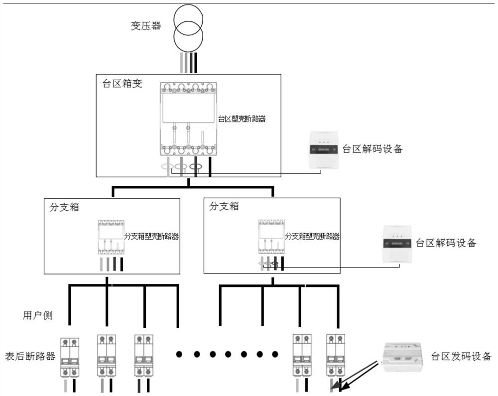
[0043] Such as figure 1As shown, a station area is generally divided into three levels. The top level is the box transformer where the transformer is located, and the lower level is divided into the branch box of the second level. There can be multiple branch boxes scattered in a tree shape; It is connected to each user electric meter on the user side in a tree form and the circuit breaker behind the meter. The present invention connects the code-sending equipment in the household-transformation relationship identification system of the station area to the fire-zero line of the circuit breaker behind the meter, and superimposes a traceability signal on the live line, and the traceability signal will be uploaded step by step through the power line, and the station area The decoding equipment in the household substation relationship recognition system is installed in the live wires A, B, and C of the plastic case circuit breaker of the station area box substation or branch box, ...

Embodiment 2

[0051] This implementation is further optimized on the basis of Embodiment 1, specifically:

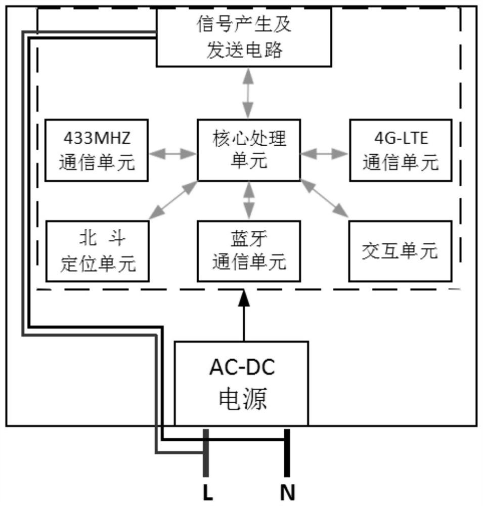
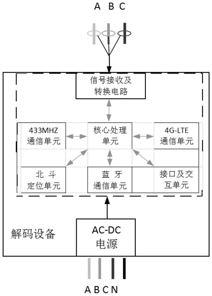
[0052] Such as Figure 4 As shown, in the communication system of the present invention, except that the traceability signal relies on the power line for transmission, other communications rely on wireless communication technology. Both the code sending device and the decoding device are embedded with a wireless communication module, which can perform wireless public network transmission and data interaction with the server. At the same time, the code sending device and the decoding device can interact with the mobile APP through Bluetooth to set related parameters, and the code sending device can also perform related address encoding. The code sending device that is powered on and working normally will apply to the server for code sending through the wireless public network, and the server will uniformly schedule and manage the code sending sequence. Since the traceability signals s...


PUM


Abstract

The invention discloses a transformer area user-transformer relation identification system based on transmitting and decoding equipment, and relates to the field of transformer area user-transformer relation identification systems, which comprises a first-stage box transformer area, a second-stage branch box area, a third-stage electric meter and a circuit breaker area behind the electric meter, and is characterized in that code transmitting equipment is connected in parallel to a live line and a null line of a circuit breaker behind the electric meter; a traceability signal is superposed on the live wire, and the traceability signal is uploaded step by step. The decoding device is installed in a live wire of a molded case circuit breaker in a box transformer area or a branch box area, is sleeved in the live wire through the open-type mutual inductor, receives a traceability signal transmitted by the code sending device through the open-type mutual inductor, converts and analyzes the signal through the processor, and finally forms readable information. The traceability of the line topology is completed, the identification of the user change relation is formed, and a topological graph can be formed through an upper application APP; according to the invention, the topology of all the user-to-change relations can be established step by step, and a set of comprehensive user-to-change relation network diagram is formed.

Description

technical field [0001] The present invention relates to the technical field of station district household change relationship identification, and more specifically relates to the technical field of station district household change relationship recognition system based on transmission and decoding equipment. Background technique [0002] In recent years, due to the frequent changes caused by the construction and development of the power grid (such as relocation, expansion, cutover, and distribution of points), the number of electricity consumers has increased, and the address of electricity consumers has changed, etc., resulting in the emergence of changes in the relationship between customers and customers. change. However, due to conditional constraints, such as line crossing, buried lines, etc., it is difficult to update the affiliation information of electricity customer meters and household transformers in a timely manner, which affects the accuracy of basic data of the...

Claims


Application Information

Patent Timeline
Patent Type & Authority Applications(China)
IPC IPC(8): H02J13/00G06Q50/06
CPCH02J13/00001H02J13/00022H02J13/00024H02J13/00026G06Q50/06Y02E60/00Y02B70/30Y02B90/20Y04S10/40Y04S20/242Y04S40/126
Inventor 杨芾藜舒永生程瑛颖谢广成刘型志苏宇周谭杰张兵
Owner 国网重庆市电力公司营销服务中心
Why Eureka
Try Eureka