
Method and device for detecting iron receiving state

A state and detection information technology, applied in image data processing, instrumentation, computing and other directions, can solve the problems of low efficiency, low efficiency of detection system, low robustness of detection algorithm, etc., to improve accuracy and enhance channel attention. Effect

Pending Publication Date: 2022-03-15
重庆赛迪奇智人工智能科技有限公司
View PDF3 Cites 0 Cited by
  • Summary
  • Abstract
  • Description
  • Claims
  • Application Information

AI Technical Summary

Problems solved by technology

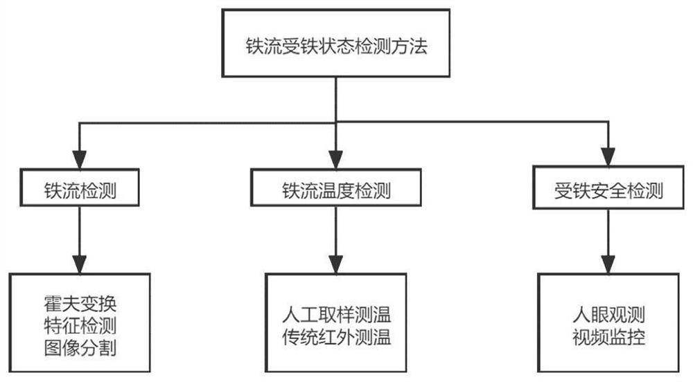
[0004] It is not difficult to understand that for iron flow detection, using traditional image processing methods, environmental factors have a great influence on the detection effect of iron flow, and the robustness of the detection algorithm is too low; Stream real-time detection, if each iron mouth separately obtains video stream for detection, the efficiency is too low for the entire detection system; for the temperature detection of iron flow, manual collection is too cumbersome, and the measurement process is discontinuous
Infrared thermal imaging camera is used for detection, and a fixed measurement area is usually set within the shooting range. If the iron flow fluctuates greatly, the temperature of the iron flow may not be measured.
For the safety detection of iron receiving, manual observation is used to judge whether a large amount of iron flow is sprayed out of the tank car by human eyes. The efficiency is too low, and only random inspection can be carried out, and real-time detection cannot be carried out.

Method used


Image

  • Method and device for detecting iron receiving state
  • Method and device for detecting iron receiving state
  • Method and device for detecting iron receiving state

Examples


Embodiment Construction

[0041] The technical solutions in the embodiments of the present application will be described below with reference to the drawings in the embodiments of the present application.

[0042] It should be noted that like numerals and letters denote similar items in the following figures, therefore, once an item is defined in one figure, it does not require further definition and explanation in subsequent figures. Meanwhile, in the description of the present application, the terms "first", "second" and the like are only used to distinguish descriptions, and cannot be understood as indicating or implying relative importance.

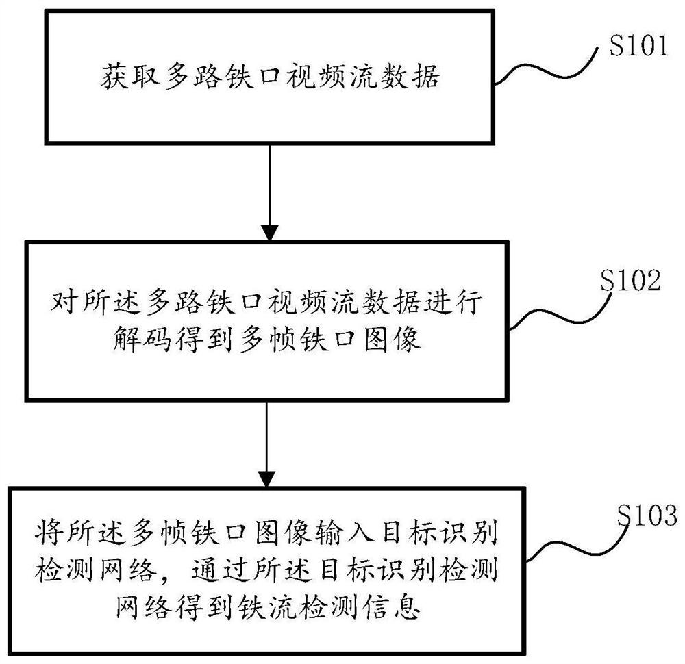
[0043] At least in order to overcome many problems in the background technology section, some embodiments of the present application need to obtain multiple video stream data for iron flow detection, and use GPU decoding framework to decode video frames, and then input the image frames into the target recognition The detection network greatly improves the effi...


PUM


Abstract

The embodiment of the invention discloses a method and a device for detecting an iron receiving state. The method comprises the following steps: acquiring multi-channel iron notch video stream data; decoding the multi-channel iron notch video stream data to obtain a plurality of frames of iron notch images, each iron notch corresponding to at least one frame of iron notch image; the multiple frames of iron notch images are input into a target recognition and detection network, iron flow detection information of at least part of iron notches is obtained through the target recognition and detection network, and the target recognition and detection network comprises a multi-scale feature extraction module, a channel attention module and a prediction regression module; the multi-scale feature extraction module is configured to obtain feature maps of different scales of the same iron notch based on an input iron notch image, and the channel attention module is used for enhancing channel attention of the feature maps. And the prediction regression module is configured to obtain the iron flow detection information of the at least part of iron notches according to the feature map output by the channel attention module.

Description

technical field [0001] The present application relates to the field of iron receiving state detection, and specifically, embodiments of the present application relate to a method and device for detecting iron receiving state. Background technique [0002] Blast furnace smelting is a continuous process of reducing iron ore into pig iron, and molten iron is the main product of the blast furnace. When tapping the blast furnace, the iron cans (also known as torpedo cans, iron ladles) are generally transported to the corresponding iron mouth, and then the molten iron is filled into the iron cans. Each iron can is ironed once from the beginning of containing the molten iron to the end. It is particularly important to detect the state of the iron flow in real time during the process of receiving iron. The detection content mainly includes iron flow detection, iron receiving safety detection, and iron flow temperature detection. [0003] Existing detection methods such as figure 1...

Claims


Application Information

Patent Timeline
Patent Type & Authority Applications(China)
IPC IPC(8): G06T7/00G06T7/11G06T7/33G06T7/62G06T7/80G06T5/50
CPCG06T7/0004G06T7/11G06T7/33G06T5/50G06T7/80G06T7/62G06T2207/10016G06T2207/10048G06T2207/20221G06T2207/30136
Inventor 刘仕通张成杰雷翔张志勇
Owner 重庆赛迪奇智人工智能科技有限公司
Learn More