
Mesoscale forming limit bending sample, preparation method and mechanical measurement method

A forming limit and bending technology, applied in the field of strain measurement, can solve the problems of the thickness of the paint on the surface of the sample, the large influence of the bending mechanical properties and resilience performance, and the inability to effectively guide the optimization of the forming process, and achieve the effect of clear outline.

Pending Publication Date: 2022-03-15
HARBIN INST OF TECH AT WEIHAI
View PDF0 Cites 0 Cited by
  • Summary
  • Abstract
  • Description
  • Claims
  • Application Information

AI Technical Summary

Problems solved by technology

However, this method is only applicable to the continuous optical path between the surface of the tested sample and the measuring lens, so this method is also unable to complete the strain measurement of the surface where the sample contacts the punch, and due to the small thickness of the thin plate at the mesoscopic scale, The bending deformation resistance is low, and the surface of the sample is relatively thickly sprayed with paint, which has a great influence on the bending mechanical properties and resilience properties of the sample, and it is impossible to accurately measure the bending deformation behavior of the metal sheet at the mesoscopic scale, so that the bending process can be further optimized restricted
[0008] It can be seen that the above two methods cannot accurately measure the strain data of the upper and lower surfaces of the sample during the bending deformation process due to their respective limitations, resulting in a reduction in the accuracy of the inability to effectively guide the optimization of the forming process

Method used


Image

  • Mesoscale forming limit bending sample, preparation method and mechanical measurement method
  • Mesoscale forming limit bending sample, preparation method and mechanical measurement method
  • Mesoscale forming limit bending sample, preparation method and mechanical measurement method

Examples


Embodiment 1

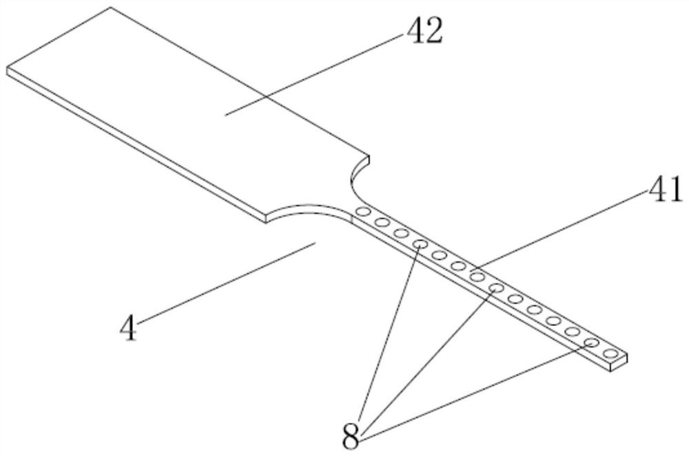
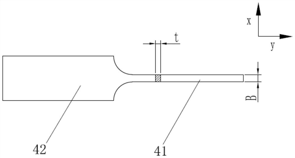
[0057] Depend on figure 1 , figure 2 As shown, the present invention provides a mesoscale forming limit bending specimen, which is provided with a wide clamping part 42 and a narrow and long test part 41, preferably composed of two parts: the wide part clamping part 42 and the narrow and long test part 41 One-piece structure; the clamping part 42 of the wide part is connected to one end of the long and narrow test part 41, and the metal coating 8 is magnetron sputtered on the upper and lower surfaces of the long and narrow test part 41, and the metal coating 8 is used as the mechanical performance test of the bending sample 4 The strain mark; the metal coating 8 is a plurality of tiny circles with mesoscopic dimensions distributed in an array, and the thickness of the metal coating 8 is no more than 200nm.

[0058] The metal coating 8 is preferably distributed in a rectangular array, and the diameter D of the metal coating 8 is 0 It can be 100 μm.

[0059] The size of the ...

Embodiment 2

[0064] The invention provides a method for preparing a mesoscale forming limit bending sample, which comprises the following steps:

[0065] (1) prepare the bending sample 4 described in embodiment 1, the material is pure copper, and the thickness t of the bending sample 4 is no more than 0.2mm;

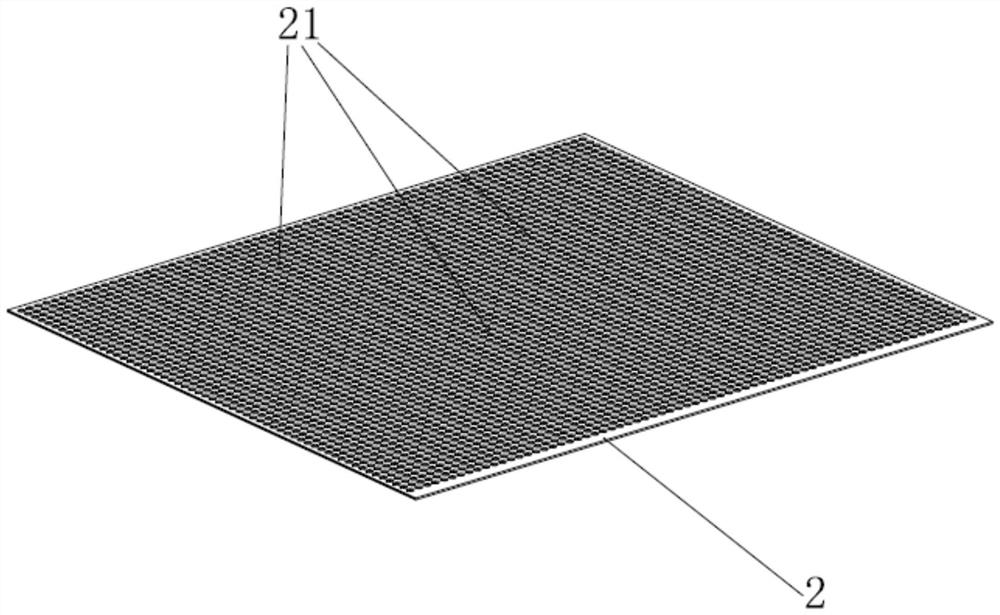
[0066] (2) Prepare a pair such as image 3 The metal-coated forming plate 2 shown is a plate-shaped structure, which is provided with a plurality of first through holes 21 of mesoscopic microscopic geometric figures, and the first through holes 21 are distributed in an array. A through hole 21 is adapted to the size and distribution of the metal coating 8;

[0067](3) A pair of metal-coated forming plates 2 are tightly covered and attached to the upper and lower surfaces of the long and narrow test portion 41 of the bending sample 4; usually the width of the metal-coating forming plate 2 is required to be greater than the width of the long and narrow test portion 41 of the bending s...

Embodiment 3

[0077] In embodiment 2, a pair of metal-coated formed plates 2 are completely tightly covered and attached to the upper and lower surfaces of the elongated test portion 41 of the bending sample 4, and existing technical means such as clamping the two firmly with clips can be used, or The magnetron sputtering forming device of the present invention is adopted.

[0078] Depend on Figure 7-Figure 10 As shown, the magnetron sputtering forming device for the metal coating 8 of the narrow and long test part 41 of the bending sample 4, the magnetron sputtering forming device is provided with a hollow frame 1, a sample positioning frame 5, and a pair of pressing plates 3 , and a pair of metal-coated forming plates 2 described in embodiment 2; by Figure 10 As shown, the sample positioning frame 5 is provided with a placement through hole 51 for placing the bending sample 4, and the placement through hole 51 matches the shape and size of the bending sample 4; the number of placement ...


PUM

PropertyMeasurementUnit
thicknessaaaaaaaaaa
diameteraaaaaaaaaa
thicknessaaaaaaaaaa

Abstract

The invention provides a mesoscale forming limit bending sample, a preparation method and a mechanical measurement method, and solves the problem that the existing strain distribution measurement method of the mesoscale forming limit bending sample cannot meet the bending mechanical measurement of the sample in a low-transparency medium environment. The mesoscale forming limit bending sample is composed of a wide part clamping part and a long and narrow testing part, the wide part clamping part is connected to one end of the long and narrow testing part, and the mesoscale forming limit bending sample is characterized in that metal coating films are respectively arranged on the upper surface and the lower surface of the long and narrow testing part through magnetron sputtering; the metal coating is a plurality of micro circles with mesoscale and is distributed in an array mode, and the thickness of the metal coating does not exceed 200nm. The invention further discloses a preparation method and a mechanical measurement method of the mesoscale forming limit bending sample, and the mesoscale forming limit bending sample can be widely applied to the technical field of strain measurement.

Description

technical field [0001] The application relates to the technical field of strain measurement, in particular to a mesoscale forming limit bending specimen, a preparation method and a mechanical measurement method. Background technique [0002] With the development of microelectronics and micromechanical industries, the demand for thin-plate micro-components is increasing. However, due to the existence of the scale effect of plastic deformation at the mesoscopic scale, the plastic deformation capacity of metal thin plates is different from that of macroscopic conditions. To improve The plastic microforming process requires a systematic study of the plastic deformation behavior of metal sheets at the mesoscopic scale. [0003] Among them, since the bending process accounts for a large proportion in the thin plate plastic micro-forming process, especially in the forming process of the micro-lead frame, the micro-bending process plays an important role. In the macrobending proces...

Claims


Application Information

Patent Timeline
Patent Type & Authority Applications(China)
IPC IPC(8): G01N3/20G01N3/06G01N1/28G01N1/32G01B11/16
CPCG01N3/20G01N3/068G01N1/286G01N1/32G01B11/16G01N2203/0003G01N2203/0023G01N2203/0298G01N2203/0641G01N2203/0682G01N2001/2886
Inventor 陈刚王瀚张鹏朱强王传杰
Owner HARBIN INST OF TECH AT WEIHAI
Learn More