
Anti-static aluminum-plastic composite packaging bag and processing equipment thereof

A technology of aluminum-plastic composite and processing equipment, which is applied in the direction of packaging, transportation, packaging, bags, etc., can solve the problems of inconvenient anti-pressure protection, inconvenient partition operation, etc., and achieve the effect of avoiding mutual contact, collision, and isolated positions

Active Publication Date: 2022-03-15
黄山源点新材料科技有限公司
View PDF12 Cites 0 Cited by
  • Summary
  • Abstract
  • Description
  • Claims
  • Application Information

AI Technical Summary

Problems solved by technology

[0005] The purpose of the present invention is to provide an antistatic aluminum-plastic composite packaging bag and its processing equipment to solve the problems that the aluminum-plastic composite packaging bag proposed in the above-mentioned background technology is inconvenient for anti-pressure protection and inconvenient for partition operation.

Method used


Image

  • Anti-static aluminum-plastic composite packaging bag and processing equipment thereof
  • Anti-static aluminum-plastic composite packaging bag and processing equipment thereof
  • Anti-static aluminum-plastic composite packaging bag and processing equipment thereof

Examples


Embodiment 1

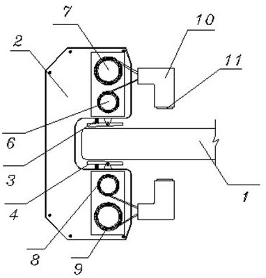
[0034] see Figure 1-2 and Figure 5-8 , comprising: a bag body 1, the side of the bag body 1 is provided with a mounting seat 2, and the inner wall of the mounting seat 2 is connected to a splint 4 on a rotating shaft, and a return spring 3 and a splint 4 are fixed between the splint 4 and the mounting seat 2 There are two symmetrically arranged in the mounting seat 2, and the splint 4 is elastically rotated in the mounting seat 2 by the return spring 3, and the initial position of the splint 4 is inclined; including the base 19, the right side of the base 19 top is fixed with a fixed frame 20 , and the first motor 21 is embedded in the fixed frame 20, and the output end of the first motor 21 is connected with the first screw 22, the bearing of the first screw rod 22 is installed in the adjustment groove 23, and the adjustment groove 23 is opened in the fixed frame 20, and the first threaded rod 22 is provided with an adjustment block 24, and the inside of the adjustment blo...

Embodiment 2

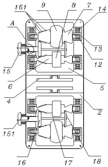
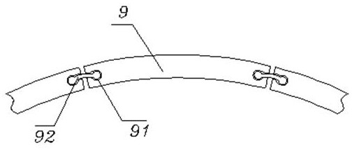
[0036] see Figure 1-3 , also includes: a mounting groove 5, the mounting groove 5 is opened in the mounting seat 2, and the first guide roller 6 and the second guide roller 7 are respectively placed in the mounting groove 5 from the inside to the outside, and the first guide roller 6 and the second guide roller The two guide rollers 7 are respectively wound with a bonded magnet fixed sheet 8 and a support bar 9, and one end of the bonded magnet fixed sheet 8 and the support bar 9 runs through the mounting seat 2 and is connected with a fixed block 10, and the fixed block 10 is bonded with a The magnetic sheet 11 and the support bar 9 are made up of arc segments of a plurality of memory alloy materials, and the side of the support bar 9 arc segments is provided with a side groove 91, and a rubber strip 92 is embedded in the side groove 91, and the rubber strip 92 Both ends are designed in a spherical structure, and the side groove 91 at one end of the rubber strip 92 is design...

Embodiment 3

[0038] see Figure 1-4 , both ends of the first guide roller 6 and the second guide roller 7 are connected in the movable seat 13 by the torsion spring 12, and the movable seat 13 is slidably installed on the side wall of the mounting groove 5 by the movable spring 14, the mounting seat 2 An adjustment rod 15 is installed on the outside through a telescopic spring 151, and one end bearing of the adjustment rod 15 is connected with a bevel gear 16, and the bevel gear 16 is located between the first guide roller 6 and the second guide roller 7, and the first guide roller 6 and the second guide roller 7 are fixed with a rack 161, and one end of the bevel gear 16 is connected with a push ring 18 through a push rod 17, and the push ring 18 is located at a recessed position at one end of the first guide roller 6 and the second guide roller 7, The side depression of the adjustment rod 15 is elastically installed with the locking rod 153 by the locking spring 152, and one end of the l...


PUM


Abstract

The invention discloses an anti-static aluminum-plastic composite packaging bag and processing equipment thereof.The anti-static aluminum-plastic composite packaging bag comprises a bag body, the side of the bag body is sleeved with a mounting base, a clamping plate is connected to the inner wall of the mounting base through a rotating shaft, and a reset spring is fixed between the clamping plate and the mounting base; the device further comprises a mounting groove, the mounting groove is formed in the mounting base, a first guide roller and a second guide roller are placed in the mounting groove from inside to outside, one end of the bonded magnet fixing piece and one end of the supporting strip penetrate through the mounting base to be connected with a fixing block, and the two ends of the first guide roller and the two ends of the second guide roller are connected into the movable base through torsional springs. An adjusting rod is installed on the outer side of the installation base in a penetrating mode through a telescopic spring, and one end of the bevel gear is connected with a push ring through a push rod. According to the anti-static aluminum-plastic composite packaging bag and the processing equipment thereof, electronic products can be fixed in the packaging bag in a partitioned mode, mutual interference is avoided, meanwhile, the electronic products of different specifications are subjected to compression resistance protection, and damage in the transportation and using process is avoided.

Description

technical field [0001] The invention relates to the technical field of aluminum-plastic composite packaging bags, in particular to an antistatic aluminum-plastic composite packaging bag and processing equipment thereof. Background technique [0002] Aluminum-plastic composite packaging bags have the characteristics of anti-static, anti-ultraviolet, moisture-proof and fresh-keeping, and are easy to process. They are widely used in food packaging, pharmaceutical packaging, and electronic product packaging. However, the existing aluminum-plastic composite packaging bags have the following problems in use : [0003] When aluminum-plastic composite packaging bags are used for electronic products or medicines, they are usually packaged and transported in batches. The existing aluminum-plastic composite packaging bags are not convenient for pressure protection. During batch transportation, they are easily compressed and cause damage to internal electronic devices At the same time,...

Claims


Application Information

Patent Timeline
Patent Type & Authority Applications(China)
IPC IPC(8): B65D30/10B65D33/00B65D85/86B31B70/81B31B70/74B31B70/04B31B170/00
CPCB65D31/00B65D33/00B65D85/00B31B70/04B31B70/74B31B70/81B31B2170/00B65D2585/86Y02W30/80
Inventor 黄亮俞宙卢磊磊孙争光金海勇方波
Owner 黄山源点新材料科技有限公司
Learn More