Efficient pharmaceutical reaction kettle stirring equipment and use method thereof
A technology of stirring equipment and reactor, which is applied in the field of high-efficiency pharmaceutical reactor stirring equipment, can solve the problems of drug mixing influence, slow production efficiency, etc., and achieve the effects of increasing production, reducing production rate, and shortening the time consumed
- Summary
- Abstract
- Description
- Claims
- Application Information
AI Technical Summary
Problems solved by technology
Method used
Image
Examples
Embodiment 1
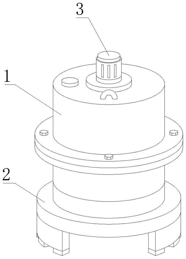
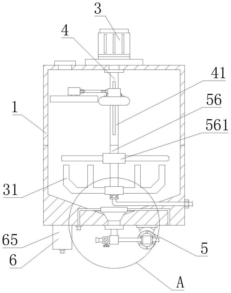
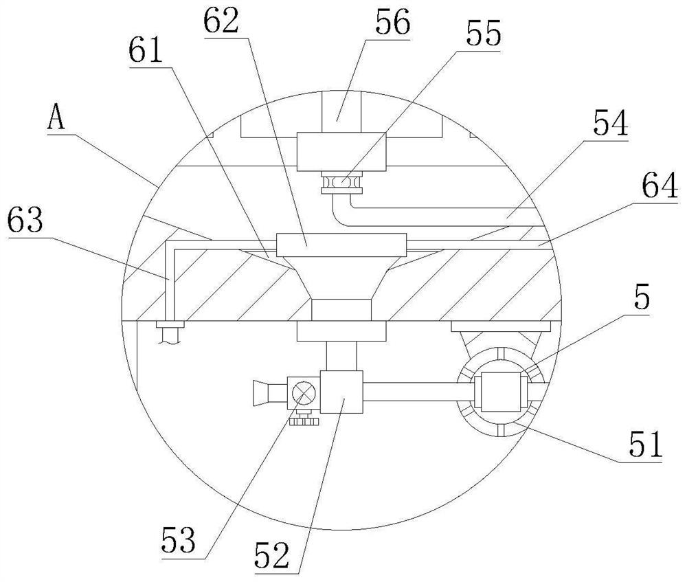
[0042] First aspect, such as Figure 1-10 As shown, the present invention provides a high-efficiency pharmaceutical reactor stirring equipment, including a drug reactor body 1, a lifting base 2 is fixedly installed on the bottom of the drug reactor body 1, and a mixing motor is fixedly installed on the top of the drug reactor body 1 3. The output shaft of the mixing motor 3 extends into the inner cavity of the drug reactor body 1. The top of the inner cavity of the drug reactor body 1 is provided with a floating defoaming mechanism 4, and the middle part of the inner cavity of the drug reactor body 1 is equipped with a high-efficiency mixing Mechanism 5, the bottom of the inner cavity of the drug reaction kettle body 1 is provided with a rapid heating mechanism 6, the floating defoaming mechanism 4 includes an extension main rod 41, the top of the extension main rod 41 is fixedly welded to the output shaft of the mixing paddle 31, and the extension main rod 41 A chute 42 is pr...
Embodiment 2
[0044] Such as Figure 1-10 As shown, on the basis of Embodiment 1, the present invention provides a technical solution: preferably, the top of the fixed box 46 inner cavity is fixedly installed with an elastic seat 47, and the bottom of the elastic seat 47 is fixedly installed with a vibration generating box 48, and the vibration Vibration motor 49 is fixedly installed in the inner chamber of box 48, and the bottom of vibration box 48 is fixedly equipped with defoaming frame 491. A center net plate 493 is fixedly installed in the center, T-shaped connecting frames 494 are fixedly connected to both sides of the central net plate 493, and a defoaming cone 495 is fixedly installed on the side of the T-shaped connecting frame 494 far away from the central net plate 493. A bent defoaming strip 4951 is fixedly installed on the outer wall of the cone thorn 495, and a diversion hollow ball 4952 is fixedly installed on the end of the defoaming cone 495 away from the T-shaped connectin...
Embodiment 3
[0046] Such as Figure 1-10 As shown, on the basis of Embodiment 1, the present invention provides a technical solution: preferably, the top of the rotary joint 55 is rotatably connected with a hollow tube 56, and the outer wall of the hollow tube 56 is fixedly equipped with a mixing paddle 31, and the hollow tube 56 The top of the top and the bottom of the extension main rod 41 are fixedly welded, the outer wall of the hollow tube 56 is fixedly connected with a dispersing ring 561, the outer wall of the dispersing ring 561 is fixedly connected with a dispersing tube 562, and the outer wall of the dispersing tube 562 is fixedly connected with an extension tube 563 , the outer wall of the extension pipe 563 is fixedly welded with a dispersion guide cover 564, which controls the operation of the circulation pump 51, and can absorb the precipitated medicine at the bottom of the inner cavity of the drug reaction kettle body 1 through the three-way pipe 52, and then circulate throug...
PUM
 Abstract
Description
Claims
Application Information
 - R&D Engineer
- R&D Manager
- IP Professional
- Industry Leading Data Capabilities
- Powerful AI technology
- Patent DNA Extraction
Browse by: Latest US Patents, China's latest patents, Technical Efficacy Thesaurus, Application Domain, Technology Topic, Popular Technical Reports.
© 2024 PatSnap. All rights reserved.Legal|Privacy policy|Modern Slavery Act Transparency Statement|Sitemap|About US| Contact US: help@patsnap.com


