Electronically commutated electric machine, brake device and method for producing electronically commutated electric machine

An electronic commutation and rotor technology, applied in the manufacture of motor generators, brakes, electric components, etc., to achieve the effect of simple interchangeability and large installation space

Pending Publication Date: 2022-03-11
ROBERT BOSCH GMBH
View PDF1 Cites 0 Cited by
  • Summary
  • Abstract
  • Description
  • Claims
  • Application Information

AI Technical Summary

Problems solved by technology

The necessary holding elements and the central bore at the rotor shaft cause additional costs

Method used


Image

  • Electronically commutated electric machine, brake device and method for producing electronically commutated electric machine
  • Electronically commutated electric machine, brake device and method for producing electronically commutated electric machine
  • Electronically commutated electric machine, brake device and method for producing electronically commutated electric machine

Examples


Embodiment Construction

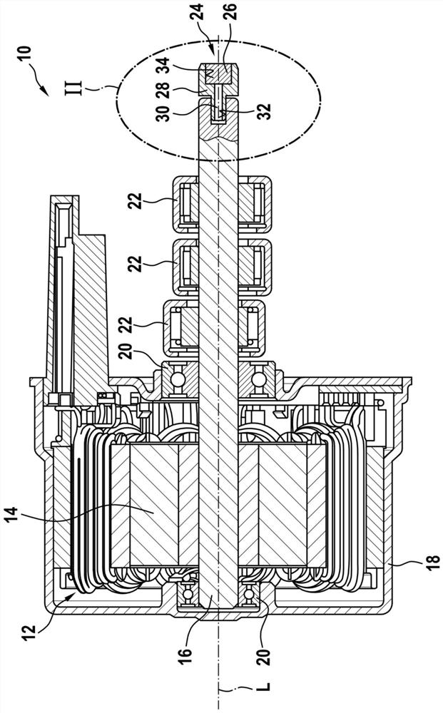
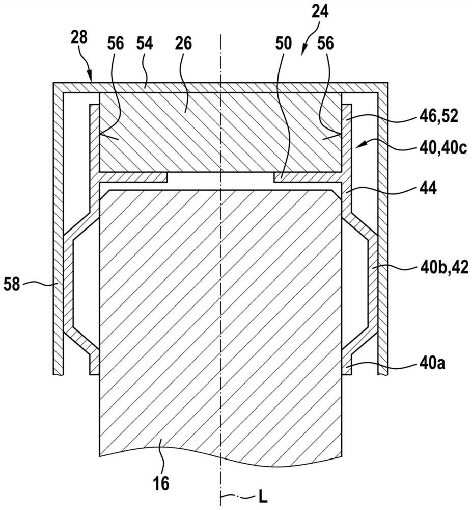
[0021] figure 2 The end of the rotor shaft 16 of an electronically commutated electric machine equipped with a signal transmitter 24 is shown. This end is situated opposite a second, unmarked end on which the rotor of the electric machine is mounted, cf. figure 1 . The rotor shaft 16 always has a constant outer diameter and is cut perpendicular to the longitudinal axis L, thus having a shaft end side oriented perpendicular thereto. The transition from the shaft end side to the shaft circumference is designed as a chamfered bevel, but can also alternatively be embodied as a rounded corner.

[0022] A clamping body 40 in the form of a tolerance ring is attached to the illustrated end of the rotor shaft 16 . The clamping body 40 is embodied as a cylindrical sleeve, which can be embodied closed on the circumferential side or slotted on the circumferential side. Slotted sleeves can be produced cost-effectively by bending sheet metal strips.

[0023] Seen in the direction of t...


PUM


Abstract

The invention relates to an electronically commutated electric machine, a brake system and a method for producing an electronically commutated electric machine, in particular an electronically commutated electric machine, having a rotor (14) on a rotor shaft (16) which can be actuated for rotational movement. In order to detect the angle of rotation of the rotor shaft (16), a signal transmitter (24) is provided, which comprises a holding element (28) and a magnetic element (26) arranged on the holding element. According to the invention, a clamping body (40) for fastening the holding element (28) to the rotor shaft (16) is proposed, which clamping body is configured with at least one fastening part (50, 52) which acts on the magnetic element (26) in the assembled state and prevents a translational movement and a rotational movement of the magnetic element (26) relative to the holding element (28). The proposed solution is designed to cancel a known adhesive connection between the magnetic element (26) and the holding element (28).

Description

technical field [0001] The invention relates to an electronically commutated electric motor according to the features of the preamble of claim 1 , an electronically commutated braking system with an electronically commutated electric motor according to the features of the preamble of claim 10 , and according to claim 11 or the method of the preamble of 12 for the manufacture of an electronically commutated electric machine. Background technique [0002] Electronically commutated electric motors are used, for example, as drive units in electronically slip-controllable brake systems of motor vehicles in order to drive a pressure generator for brake pressure regulation. In this case, the electric motor is actuated electrically as required by the electronic controller of the brake system. In the case of electrical actuation, the pressure generator supplies pressure medium in the brake circuit. Accordingly, a brake pressure builds up in the engaged wheel brakes proportional to ...

Claims


Application Information

Patent Timeline
Patent Type & Authority Applications(China)
IPC IPC(8): H02K29/08H02K11/215H02K15/00
CPCH02K29/08H02K11/215H02K15/00B60T17/02B60T8/4018H02K11/35H02K7/003H02K7/12B60T8/176B60T13/74B60Y2400/81
Inventor E·辛恩尔
Owner ROBERT BOSCH GMBH
Why Eureka
Try Eureka