Distribution network overhead line pole erecting and removing device

A technology for overhead lines and poles, which is applied in the direction of overhead lines/cable equipment, towers, building types, etc. It can solve problems such as the inability to guarantee the personal safety of operators, threats to personal and power grid equipment, and hidden dangers of falling objects. The effect of improving operation efficiency, optimizing operation links, and ensuring safety

Pending Publication Date: 2022-03-11
STATE GRID SHANDONG ELECTRIC POWER COMPANY WEIFANG POWER SUPPLY +1
View PDF0 Cites 0 Cited by
  • Summary
  • Abstract
  • Description
  • Claims
  • Application Information

AI Technical Summary

Problems solved by technology

The above-mentioned operation method has potential safety hazards of falling objects from high places. No matter whether ordinary hoisting belts or steel wire ropes are selected, a firm connection point with the pole cannot be established. During the lifting process of the pole, sliding friction is likely to cause the pole to fall, which is harmful to people, Serious threat to power grid and equipment
On the other hand, during the process of the pole falling and fixing, it is necessary to manually rotate the pole to adjust the direction to meet the position of the wire and the cross arm. However, during the rotation of the pole, the personal safety of the workers cannot be guaranteed.

Method used


Image

  • Distribution network overhead line pole erecting and removing device
  • Distribution network overhead line pole erecting and removing device
  • Distribution network overhead line pole erecting and removing device

Examples


Embodiment Construction

[0028] In order to make the purpose and technical solution of the present invention clearer, the present invention will be further described in detail below in conjunction with the accompanying drawings.

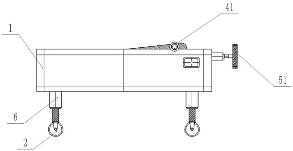
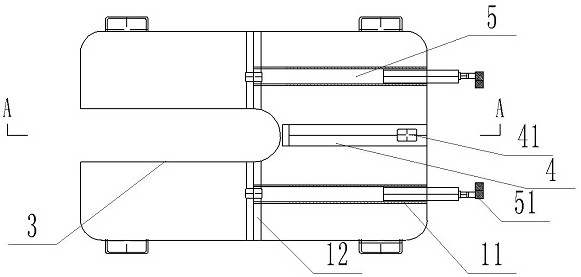
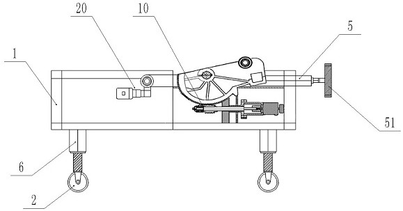
[0029] Such as Figure 1~Figure 3 As shown, a kind of vertical withdrawal pole device for distribution network overhead lines according to the present invention includes a chassis 1 and a control mechanism. Mechanically driven and assisted, the control module controls the movement of the moving wheel 2, which is used for the movement of the vertical withdrawal rod device within a short distance. At the same time, preferably, the moving wheel 2 has a locking mechanism and a self-locking function to ensure that it is firmly fixed in the operation project at the target location.

[0030] The front part of the chassis 1 is provided with a pole channel plate 3. The pole channel plate 3 is an open slot from the middle of the chassis 1 to the front through the chassis 1 vertically...


PUM


Abstract

The invention relates to the technical field of distribution network maintenance, in particular to a distribution network overhead line electric pole erecting and removing device. The device comprises a chassis and a control mechanism, and an electric pole channel disc is arranged on the front portion of the chassis; an electric pole root supporting mechanism is hinged to the upper surface of the base plate on the rear portion of the closed portion of the electric pole channel plate, telescopic holding arms are arranged on the two sides of the middle rear portion of the upper surface of the base plate respectively, and holding grippers are arranged at the ends of the telescopic holding arms; sliding rails extending from the outer portion of the closed opening of the electric pole channel disc to the periphery of the base plate are arranged in the middle of the upper surface of the base plate in the longitudinal direction, and sliding seats are arranged in the sliding rails and connected with the telescopic holding arms through coupling pieces. By means of the device, the safety and reliability of electric pole erecting and removing work can be effectively guaranteed, the mode of high-altitude electric pole moving is replaced with ground operation, the operation safety is remarkably improved, the operation links are optimized, the operation efficiency is improved, the electric pole does not need to be hoisted through a crane, the construction links are reduced, and the operation efficiency is obviously improved.

Description

technical field [0001] The invention relates to the technical field of distribution network maintenance, in particular to a vertical removal pole device for overhead lines of a distribution network. Background technique [0002] Distribution network overhead lines are the main form of distribution network lines at present. The overhead lines have a simple structure and are convenient for operation and maintenance. The distribution network project that erects or removes the electric pole. [0003] At present, the common erection and removal pole operations are divided into two methods: live construction or blackout construction. No matter which maintenance method is adopted, the erection or removal of the pole requires the cooperation of crane lifting. Taking the electrified Xinli electric pole as an example, first fix the wire rope at the appropriate position on the upper end of the pole, then use the hook to pull the wire rope and lift it to a height of 15 meters above the...

Claims


Application Information

Patent Timeline
IPC IPC(8): H02G1/02E04H12/34
CPCH02G1/02E04H12/34
Inventor 姚文展王立勇张凯毕盛伟姜颖先于金亮赵荣升马亚琦耿维帅宋云海乔丕凡姜言刚王永霞马献辉于欣李晓林张磊辛洪杰高兴琳陈增顺曹光进张柏宗韦立坤代相波马骏鹏耿海强郎伟方立华马玉晖
Owner STATE GRID SHANDONG ELECTRIC POWER COMPANY WEIFANG POWER SUPPLY
Why Eureka
Try Eureka