Rail type revolution driving mechanism of bin discharger

A technology of driving mechanism and warehouse-out machine, which is applied in the direction of conveyors, conveyor objects, cleaning devices, etc., which can solve problems such as maintenance and complex structures, and achieve the effects of ensuring fluency, occupying small radial space, and simplifying structures

Pending Publication Date: 2022-03-11
GSS SYST SUZHOU
View PDF0 Cites 0 Cited by
  • Summary
  • Abstract
  • Description
  • Claims
  • Application Information

AI Technical Summary

Problems solved by technology

[0007] Aiming at the deficiencies of the prior art, the present invention provides a rail-type revolving drive mechanism for the bin-discharging machine, which solves the problem of maintenance and structural complexity that the revolving drive device of the bin-discharging machine is located at the end of the auger and buried in the material, and the track-type Floating connection problem between the track buckle sprocket of the warehouse-out machine and the output shaft of the revolution reducer

Method used


Image

  • Rail type revolution driving mechanism of bin discharger
  • Rail type revolution driving mechanism of bin discharger
  • Rail type revolution driving mechanism of bin discharger

Examples


Embodiment Construction

[0025] The following will clearly and completely describe the technical solutions in the embodiments of the present invention with reference to the accompanying drawings in the embodiments of the present invention. Obviously, the described embodiments are only some, not all, embodiments of the present invention. Based on the embodiments of the present invention, all other embodiments obtained by persons of ordinary skill in the art without making creative efforts belong to the protection scope of the present invention.

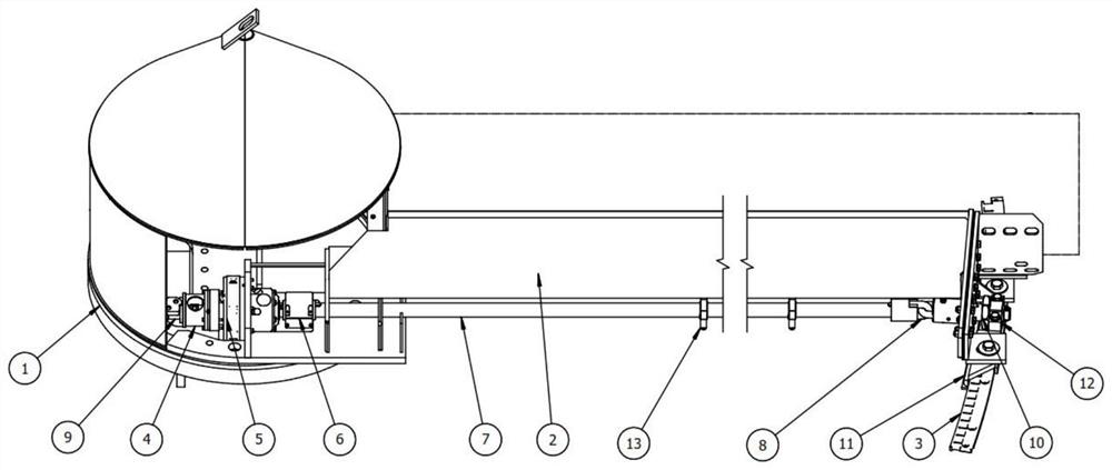
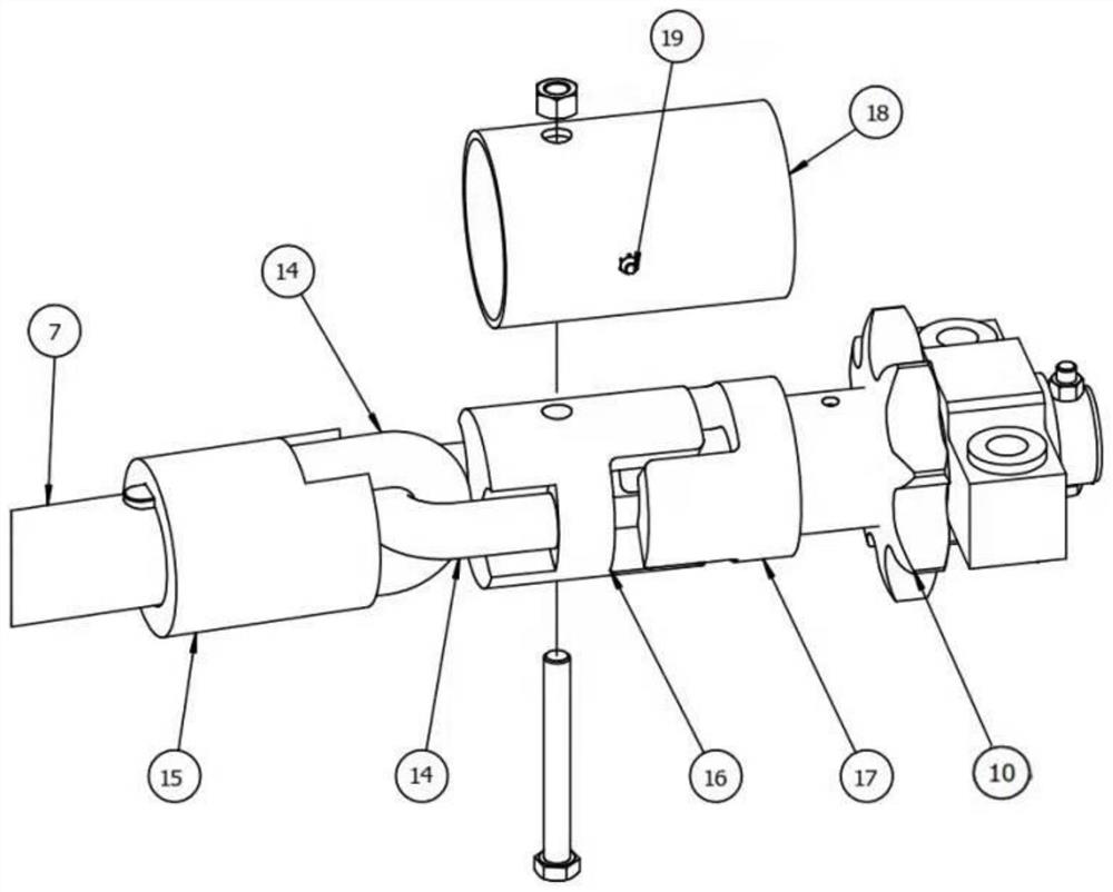
[0026] see Figure 1-3 , a orbital silo discharge machine revolution drive mechanism, including a silo and a central turntable 1, the central turntable 1 is set at the center of the silo and can rotate around the axis of the vertical silo on the machine base, and the periphery of the silo is close to the silo wall Lay a circle of track 3, the center turntable 1 is connected to the back plate 2, the other end of the back plate 2 is bolted to the track shoe 11 b...


PUM


Abstract

The invention relates to the technical field of bulk material storage, and discloses a rail-mounted warehouse discharger revolution driving mechanism which comprises a silo and a center rotating disc, the center rotating disc is arranged at the center discharging position of the silo and can rotate around the axis of the vertical silo on a machine base, a circle of rail is laid on the position, close to the silo wall, of the periphery of the silo, and the center rotating disc is connected with a back plate. The other end of the back plate is in bolted connection with a rail shoe buckled on the rail, a revolution speed reducer is installed on the back plate frame and located in the silo, and a revolution driving motor is installed at the input end of the revolution speed reducer through a flange plate. According to the invention, the revolution driving motor and the revolution speed reducer are placed in the machine room of the central turntable, so that the structure of the tail part of the warehouse discharger is simplified, the revolution resistance is reduced, and under the condition that materials are stored in the silo, personnel can enter the center machine room of the warehouse discharger from the bottom to maintain the revolution driving motor and the revolution speed reducer.

Description

technical field [0001] The invention relates to the technical field of bulk material storage, in particular to a revolution drive mechanism of a rail-type warehouse-out machine. Background technique [0002] Vertical silos are the main form of bulk material storage and are widely used in the storage of grain, feed, bulk meal, wood chips, and chemical raw materials. The silo generally has a discharge port at the bottom of the silo for the material to exit the silo, but for materials with poor self-flowing properties, it is difficult to rely on the material to flow out of the silo, and it is necessary to set up a forced discharge device at the discharge port. [0003] The central turntable of the silo auger discharger is installed at the central outlet of the silo bottom, one end of the screw conveying auger is installed on the central turntable, and the other end is close to the silo wall. When discharging, the discharge machine is buried by the material, and the screw auger...

Claims


Application Information

Patent Timeline
Patent Type & Authority Applications(China)
IPC IPC(8): B65G65/48B65G45/02
CPCB65G65/4818B65G45/02B65G2201/04
Inventor 田颖斌郭宁冯海东
Owner GSS SYST SUZHOU
Why Eureka
Try Eureka