Convex wafer workpiece grinding device

A technology for grinding devices and wafers, which is applied in the direction of grinding workpiece supports, machine tools suitable for grinding workpiece planes, grinding machines, etc., which can solve problems such as high requirements for workers' operating skills, uneven force application, and short service life of thimbles. Low operating skill requirements, reduced spherical eccentricity, and extended service life

Pending Publication Date: 2022-03-11
唐山万士和电子有限公司
View PDF0 Cites 0 Cited by
  • Summary
  • Abstract
  • Description
  • Claims
  • Application Information

AI Technical Summary

Problems solved by technology

Since the lower end of the thimble and the top surface of the suction plate require high precision, the placement position of the convex wafer workpiece must be concentric with the bottom surface of the suction plate. It is not easy to keep the thimble, suction plate and convex wafer workpiece coaxial, which is harmful to the workers. High operating skill requirements
Due to the small contact area between the lower end of the thimble and the top surface of the suction plate, it is easy to wear, resulting in uneven force, which increases the spherical eccentricity of the convex wafer workpiece (up to 120 seconds), and ultimately affects the processing quality of the convex wafer workpiece
Due to the above reasons, at present, the service life of thimbles and suction discs is short, the replacement frequency is high, and the production cost is high.

Method used


Image

  • Convex wafer workpiece grinding device
  • Convex wafer workpiece grinding device
  • Convex wafer workpiece grinding device

Examples


Embodiment Construction

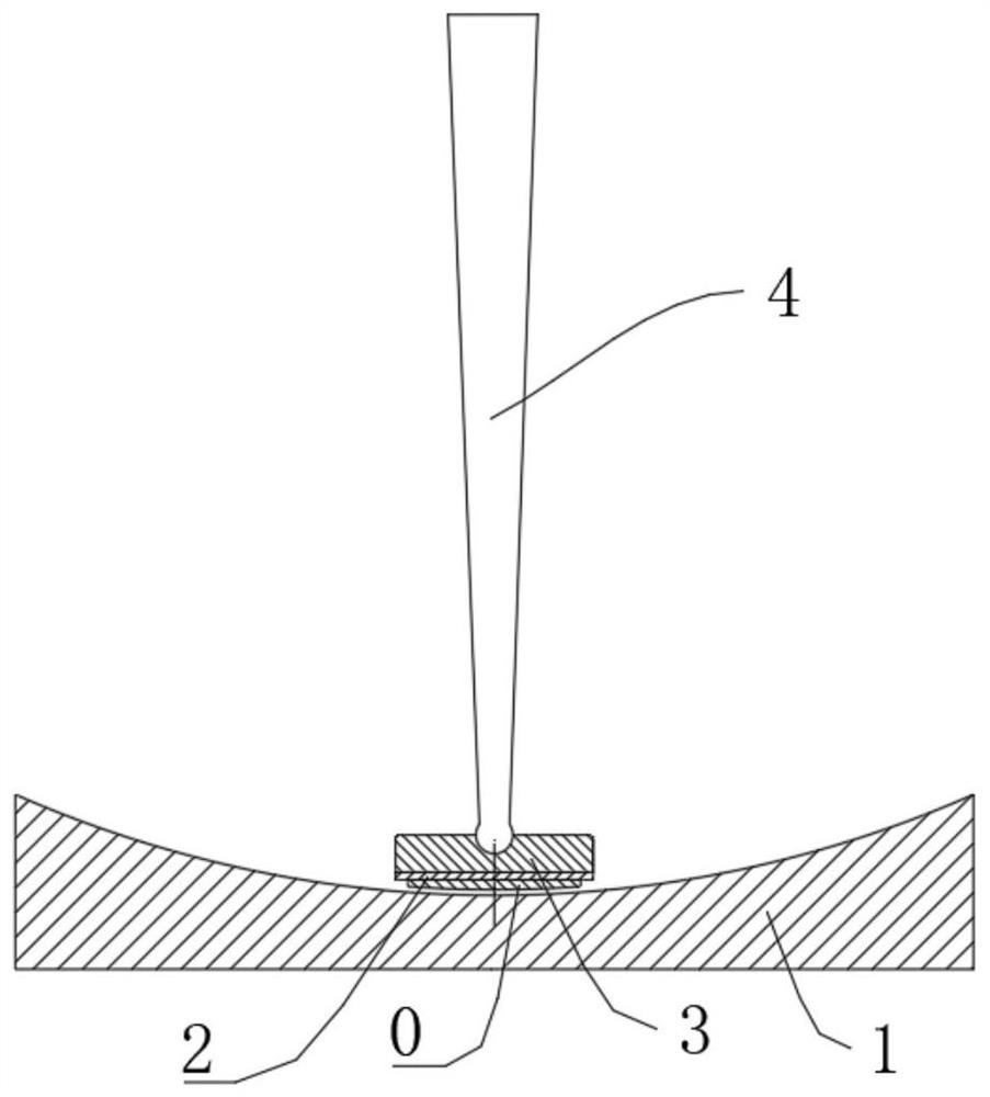
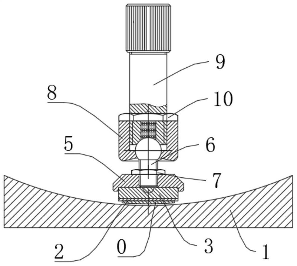
[0121] Such as Figure 2 to Figure 6 as shown,

[0122] This embodiment provides a convex wafer workpiece grinding device,

[0123] Including concave spherical grinding disc 1 and suction disc 3;

[0124] The suction disc 3 is located above the concave spherical grinding disc 1;

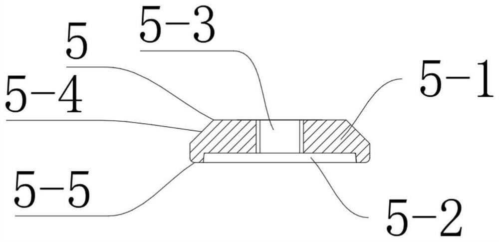
[0125] The suction disc 3 is engaged with the chuck 5;

[0126] The chuck 5 is fixedly connected to one end of the ball handle 6 through a first nut 7;

[0127] The other end of the ball handle 6 is movably connected with the lower lock nut 8 through a swing rod 9;

[0128] The lower lock nut 8 is fixedly connected to the swing rod 9 through a second nut 10 .

[0129] In this embodiment, the suction disk is engaged with the chuck; the chuck is fixedly connected to one end of the ball handle through the first nut; the other end of the ball handle is movably connected to the lower lock nut through the swing rod. The second nut is used to fix the connection between the lower lock nut and the swing...


PUM


Abstract

The invention discloses a convex wafer workpiece grinding device which comprises a concave spherical grinding disc and a wafer suction disc. The sheet suction disc is positioned above the concave spherical grinding disc; the wafer suction disc is connected with the chuck in a clamping manner; the chuck is fixedly connected with one end of the ball handle through the first nut; the other end of the ball handle is movably connected with the lower lock nut through a swing rod; the lower lock nut is fixedly connected with the swing rod through a second nut. By means of the convex wafer workpiece grinding device, a worker only needs to clamp the wafer suction disc where the convex wafer workpiece is fixed to the bottom of the chuck, accurate installation can be achieved, meanwhile, large-area contact between the wafer suction disc and the chuck is achieved, the requirement for the operation technology of the worker is low, the top face of the wafer suction disc is not prone to abrasion, and the working efficiency is improved. The wafer suction disc is simple in structure, the spherical eccentricity of the convex wafer workpiece is reduced (less than 60 seconds), the machining quality of the convex wafer workpiece is greatly improved, meanwhile, the service life of the wafer suction disc is greatly prolonged, the replacement frequency is greatly reduced, and the production cost is greatly reduced.

Description

technical field [0001] The invention relates to a grinding device, in particular to a convex wafer workpiece grinding device. Background technique [0002] Such as figure 1 As shown, the convex wafer workpiece grinding device in the prior art includes a concave spherical grinding disc 1 and a suction disc 3; the suction disc 3 is located above the concave spherical grinding disc 1; the suction disc 3 and the thimble The lower end of 4 is flexibly connected; the convex wafer workpiece 0 is fixedly connected with the suction disc 3 through the adhesive tape 2. Since the lower end of the thimble and the top surface of the suction plate require high precision, the placement position of the convex wafer workpiece must be concentric with the bottom surface of the suction plate. It is not easy to keep the thimble, suction plate and convex wafer workpiece coaxial, which is harmful to the workers. High operating skills are required. Due to the small contact area between the lower ...

Claims


Application Information

Patent Timeline
IPC IPC(8): B24B7/22B24B41/06
CPCB24B7/228B24B41/068
Inventor 李剑王丽娟袁庆祝常丽敏段洪伟马建立
Owner 唐山万士和电子有限公司
Why Eureka
Try Eureka