
On-line automatic correction steel billet continuous chamfering device

A chamfering device and automatic correction technology, applied in the directions of transportation and packaging, conveyor objects, welding equipment, etc., can solve problems such as inability to adapt to adjustment, inability to process billet chamfering, unqualified products, etc., to improve work efficiency , the effect of improving efficiency

Inactive Publication Date: 2022-03-11
杨再宾
View PDF0 Cites 0 Cited by
  • Summary
  • Abstract
  • Description
  • Claims
  • Application Information

AI Technical Summary

Problems solved by technology

[0002] The steel billet will be continuously conveyed after production and processing, coupled with the influence of the existing continuous casting process level, the steel billet produced by the continuous casting machine will usually have cracks at the four corners. If it is not cleaned, it will be directly sent to the subsequent process for processing , may make the produced products unqualified, so a chamfering device is needed to chamfer the outer edges of the four corners of the billet, but the existing chamfering device is not convenient for angle adjustment when in use, and cannot The width of the steel billet is adapted and adjusted, and at the same time, the chamfering process of the steel billet cannot be performed continuously, thereby reducing the efficiency of the billet chamfering process

Method used


Image

  • On-line automatic correction steel billet continuous chamfering device
  • On-line automatic correction steel billet continuous chamfering device
  • On-line automatic correction steel billet continuous chamfering device

Examples


Embodiment Construction

[0024] The following will clearly and completely describe the technical solutions in the embodiments of the present invention with reference to the accompanying drawings in the embodiments of the present invention. Obviously, the described embodiments are only some, not all, embodiments of the present invention. Based on the embodiments of the present invention, all other embodiments obtained by persons of ordinary skill in the art without making creative efforts belong to the protection scope of the present invention.

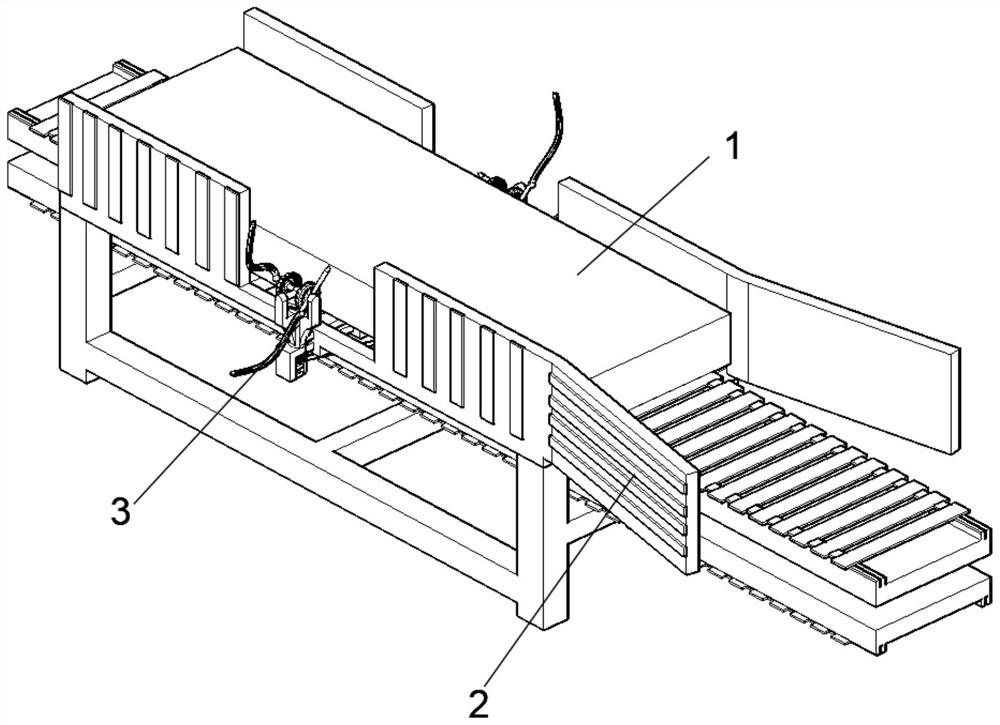
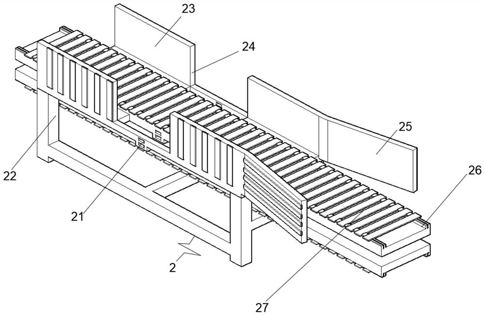
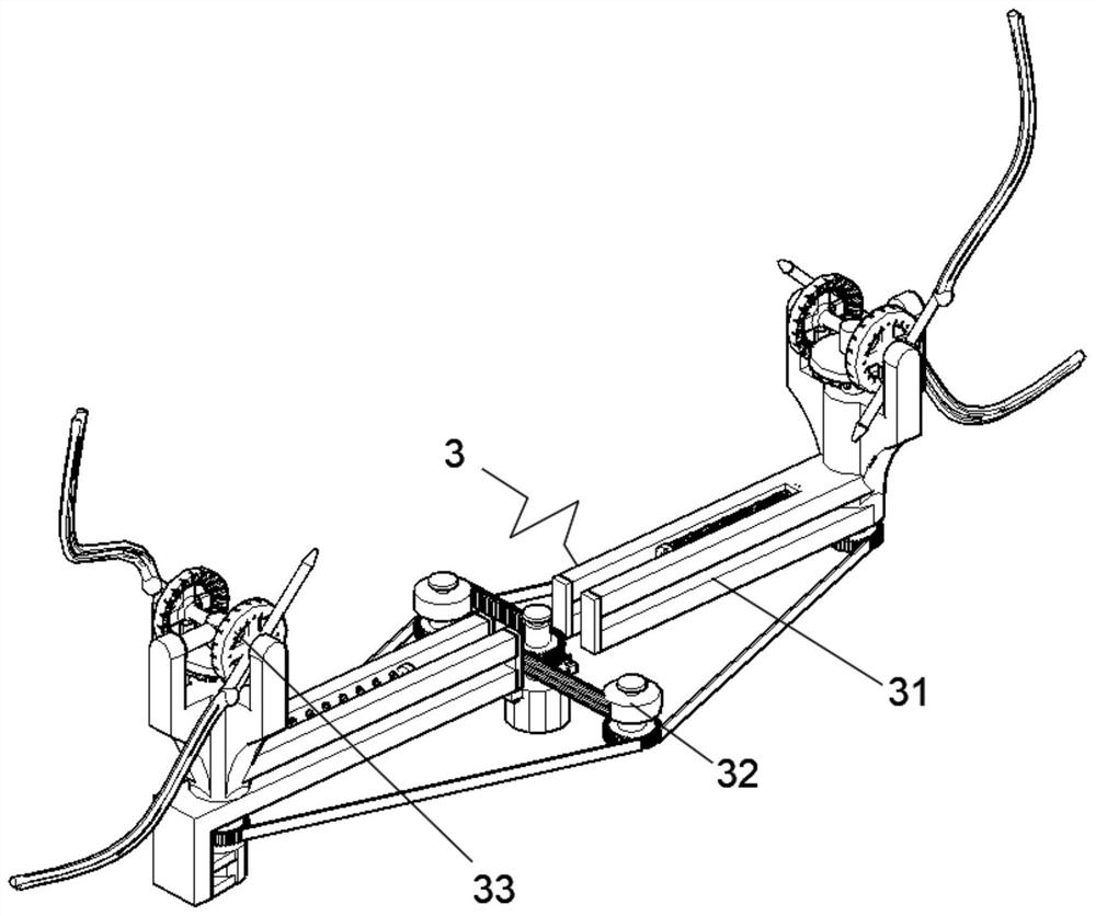
[0025] see Figure 1-6 , the present invention provides a technical solution: an online automatic correction billet continuous chamfering device, including a steel plate 1, a conveying device 2 and a chamfering device 3, the steel plate 1 is placed on the center upper surface of the conveying device 2, and the chamfering device 3 is fixed Installed in the center of the bottom surface of the conveying device 2, the inside of the conveying device 2 includes a pl...


PUM


Abstract

The invention discloses an on-line automatic correction steel billet continuous chamfering device which comprises a steel plate, a conveying device and a chamfering device, the steel plate is placed on the upper surface of the center of the conveying device, and the chamfering device is fixedly installed in the center of the bottom face of the conveying device. The conveying device internally comprises an inserting groove, a supporting frame, side plates, a groove, a correction guide plate, a limiting sliding rail and a conveying belt, the inserting groove is formed in the centers of the two side faces of the supporting frame, the side plates are symmetrically and fixedly connected to the top edges of the two side faces of the conveying device, and the groove is formed in the centers of the side faces of the side plates; the correction guide plate is fixedly connected to one end face of the side plate, and the limiting sliding rail is fixedly installed in the center of the top face of the supporting frame. According to the steel billet chamfering device, adaptive chamfering machining can be carried out on steel billets with different widths by adjusting the chamfering device, the steel billets can be automatically corrected, meanwhile, chamfering machining can be continuously carried out on the steel billets, and therefore the steel billet chamfering machining efficiency is improved.

Description

technical field [0001] The invention relates to the technical field of chamfering equipment, in particular to an online automatic correction billet continuous chamfering device. Background technique [0002] The steel billet will be continuously conveyed after production and processing, coupled with the influence of the existing continuous casting process level, the steel billet produced by the continuous casting machine will usually have cracks at the four corners, if it is not cleaned, it will be directly sent to the subsequent process for processing , may make the produced product unqualified, so a chamfering device is needed to chamfer the four corners of the outer edges of the billet, but the existing chamfering device is not convenient for angle adjustment when it is used, and it cannot be adjusted according to the The width of the steel billet is adjusted and used, and at the same time, the chamfering process of the steel billet cannot be performed continuously, there...

Claims


Application Information

Patent Timeline
Patent Type & Authority Applications(China)
IPC IPC(8): B23K7/00B23K7/10B65G47/24
CPCB23K7/00B23K7/10B65G47/24
Inventor 杨再宾
Owner 杨再宾
Learn More