Manufacturing method of stator coil of alternating current traction motor
A technology for stator coils and traction motors, which is applied in the manufacture of motor generators, electrical components, electromechanical devices, etc., can solve the problems of reducing the number of coil transfers in the manufacturing process steps of the stator coil, and the inability of machine wrapping of the noses at both ends of the stator coil, etc. Achieve the effect of realizing full-machine wrapping, reducing labor costs, and reducing production process steps
- Summary
- Abstract
- Description
- Claims
- Application Information
AI Technical Summary
Problems solved by technology
Method used
Image

Examples
Embodiment 1
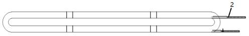
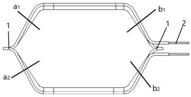
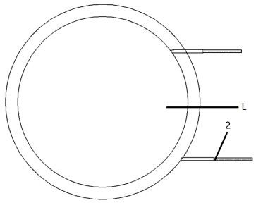
[0035] as attached Figure 1-6 As shown, the manufacturing method of the stator coil of the AC traction motor specifically includes the following steps:
[0036] S1: Wind the electromagnetic wire into a circular coil; use the circular winding core tooling on the shuttle winding machine. The core diameter of the circular winding core tooling is set according to the total length of the forming coil of different types, specifically: , according to the total length of different types of forming coils under specific working conditions, the winding diameter of the corresponding circular coil, that is, the diameter of the winding core, is derived, and then the electromagnetic wire is wound into a circular shape using the corresponding winding model tooling coil. In order to reduce the manufacturing cost of the winding mold core, those skilled in the art can design the wire winding mold core tooling as a general-purpose tooling with adjustable diameter. The circular coil after the e...
Embodiment 2
[0048] The difference between this embodiment and Embodiment 1 is that in step S1: when the electromagnetic wire is wound into a circular coil, the winding work is carried out on the winding machine of the cylindrical coil, and according to the total length of the required forming coil Size to adjust the diameter of the winding tooling to make a circular coil of the corresponding size.
Embodiment 3
[0050] The difference between this embodiment and Embodiment 1 is that in step S3: in the insulation wrapping of the circular coil, the position of the lead head of the insulation tape is manually adjusted on the workbench and the lead end is wrapped, and then the glue is automatically dispensed by the robot. The method is to carry out the beginning work of the insulation tape on the machine, and then the machine performs the whole machine insulation tape wrapping on the circular coil, and then the robot automatically dispenses glue and automatically cuts the insulation tape to carry out the finishing work of the insulation tape. The automatic dispensing of the robot is specifically as follows: the insulating tape is pulled by the finger of the robot simulator, and after the liquid glue is dipped on the insulating tape, the insulating tape is fixed on the circular coil. The robot automatically cuts the insulating tape specifically as follows: after the robot dispenses glue at t...
PUM
 Abstract
Description
Claims
Application Information
 - R&D
- Intellectual Property
- Life Sciences
- Materials
- Tech Scout
- Unparalleled Data Quality
- Higher Quality Content
- 60% Fewer Hallucinations
Browse by: Latest US Patents, China's latest patents, Technical Efficacy Thesaurus, Application Domain, Technology Topic, Popular Technical Reports.
© 2025 PatSnap. All rights reserved.Legal|Privacy policy|Modern Slavery Act Transparency Statement|Sitemap|About US| Contact US: help@patsnap.com