
New energy battery side plate film pasting device

A new energy, battery-side technology, applied in the manufacture of electrolyte batteries, non-aqueous electrolyte batteries, transportation and packaging, etc., can solve the problem of inconvenient replacement of film drums, and achieve the effect of easy replacement and easy cutting

Inactive Publication Date: 2022-03-08
深圳安博智控科技有限公司
View PDF6 Cites 1 Cited by
  • Summary
  • Abstract
  • Description
  • Claims
  • Application Information

AI Technical Summary

Problems solved by technology

[0003] The purpose of the present invention is to provide a new energy battery side panel film sticking device to solve the problem that it is inconvenient to replace the film roll when sticking the film in the above-mentioned background technology

Method used


Image

  • New energy battery side plate film pasting device
  • New energy battery side plate film pasting device
  • New energy battery side plate film pasting device

Examples


Embodiment 1

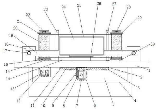
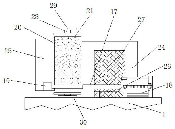
[0026] Example 1: See Figure 1-6 , a new energy battery side panel film sticking device, including a fixed platform 1 and a base 4, the bottom of the fixed platform 1 is fixedly connected with the base 4, the top of the fixed platform 1 is fixedly installed with a support seat 26, and one side of the support seat 26 is set There is a first fixed plate 23, a new energy battery body 24 is provided on the top of the support seat 26, a cylinder 18 is fixedly installed on one side of the top of the fixed table 1, a guide groove 10 is provided inside the top of the fixed table 1, and a guide groove 10 is provided inside the base 4. There is a first reserved groove 5, a first base 15 is fixedly installed on one side of the top of the fixed platform 1, a second base 30 is fixedly installed on the other side of the top of the fixed platform 1, and a second base 30 is fixedly installed on one side of the base 4 inside. Two reserved slots 12;

[0027] The inside of the second reserved ...

Embodiment 2

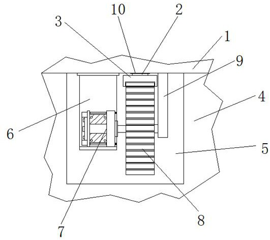
[0029] Embodiment 2: the inside of the first reserved groove 5 is fixedly installed with a fixed frame 6, and the inside of the fixed frame 6 is fixedly installed with a first drive motor 7, and the output end of the first drive motor 7 is fixedly connected with a gear 8 through a transmission shaft. One end of the gear 8 is movably connected with a mount 9, and the top of the mount 9 is fixedly connected with the bottom of the fixed table 1;

[0030] Specifically, such as figure 1 , image 3 and Image 6 As shown, open the first driving motor 7, and drive the gear 8 to rotate through the transmission shaft. Because one end of the gear 8 is provided with a mounting seat 9, at this moment, one end of the gear 8 will rotate in the interior of the mounting seat 9 one end.

Embodiment 3

[0031] Embodiment 3: the top of the gear 8 is provided with a toothed rod 3, one side of the top of the toothed rod 3 is fixedly connected with the first connecting rod 2, and the other side of the top of the toothed rod 3 is fixedly connected with the second connecting rod 11, and the first connected The top end of the rod 2 passes through the inside of the guide groove 10 and is fixedly connected with a second fixing plate 27;

[0032] The top end of the second connecting rod 11 runs through the inside of the guide groove 10 and is fixedly connected to the limit block 14. The width of the limit block 14 is greater than the width of the guide groove 10. The first connecting rod 2 and the second connecting rod 11 can be placed in the guide groove 10. The internal sliding of the gear rod 3 and the gear 8 are meshed;

[0033] Specifically, such as figure 1 , image 3 and Image 6As shown, because the top of the gear 8 is meshed with the gear rod 3, when the gear 8 rotates, th...


PUM


Abstract

The invention discloses a new energy battery side plate film pasting device which comprises a fixing table and a base, the base is fixedly connected to the bottom end of the fixing table, a supporting seat is fixedly installed at the top end of the fixing table, a first fixing plate is arranged on one side of the supporting seat, and a new energy battery body is arranged at the top end of the supporting seat. And an air cylinder is fixedly mounted on one side of the top end of the fixed table. According to the new energy battery side plate film pasting device, parts such as a film rolling barrel are arranged, a first positioning sleeve and a second positioning sleeve are screwed, the film rolling barrel can be detached, the film rolling barrel is installed outside a first connecting shaft and a second connecting shaft, a second driving motor is started, the first connecting shaft is driven to rotate through a transmission shaft, and the film rolling barrel can be detached; and when the first connecting shaft rotates, the film rolling barrel is driven to rotate, at the moment, a film body is conveyed, so that film pasting is more convenient, waste films can be conveniently and timely rolled, and the problem that the film rolling barrel is inconvenient to replace during film pasting is solved.

Description

technical field [0001] The invention relates to the technical field of film sticking devices, in particular to a new energy battery side plate film sticking device. Background technique [0002] New energy batteries can be divided into fuel cells, lithium-ion batteries and other types. New energy batteries are generally used in the field of new energy vehicles. In the process of producing new energy batteries, multiple processes are required. One of the processes is to clean the outside of the battery. The side panels are attached to the film. In the past, the new energy battery side panel film attachment device was inconvenient to replace the film roll when the film was attached, and the waste film was not easy to process and recycle in time, which made it not suitable enough; it was not convenient to fix the new energy battery when the film was attached. , resulting in easy deviation and insufficient stability during film application; at the same time, the cutting is not p...

Claims


Application Information

Patent Timeline
IPC IPC(8): B65H37/04B65H16/10B65H16/02B65H35/10H01M10/058
CPCB65H37/04B65H16/103B65H16/02B65H35/10H01M10/058B65H2701/1133Y02E60/10Y02P70/50
Inventor 陈奎
Owner 深圳安博智控科技有限公司
Learn More