Iron pan raw material handle manufacturing equipment

A technology for iron pans and handles, which is applied in the field of iron pan raw material handle manufacturing equipment, which can solve problems such as irregular curvature of handles, affecting manufacturing efficiency, and people's injuries, and achieves the effect of consistent curvature

Pending Publication Date: 2022-03-08
胡锦森
View PDF0 Cites 0 Cited by
  • Summary
  • Abstract
  • Description
  • Claims
  • Application Information

AI Technical Summary

Problems solved by technology

[0003] However, in the prior art, when manufacturing iron pan handles, it is necessary to manually bend the handle after heating the handle, and then beat the handle after bending, resulting in irregular curvature of the manufactured handle, and manual blanking after the equipment is manufactured , during the operation of the equipment, direct contact with the equipment will cause people to be injured and affect the manufacturing efficiency

Method used


Image

  • Iron pan raw material handle manufacturing equipment
  • Iron pan raw material handle manufacturing equipment
  • Iron pan raw material handle manufacturing equipment

Examples


Embodiment 1

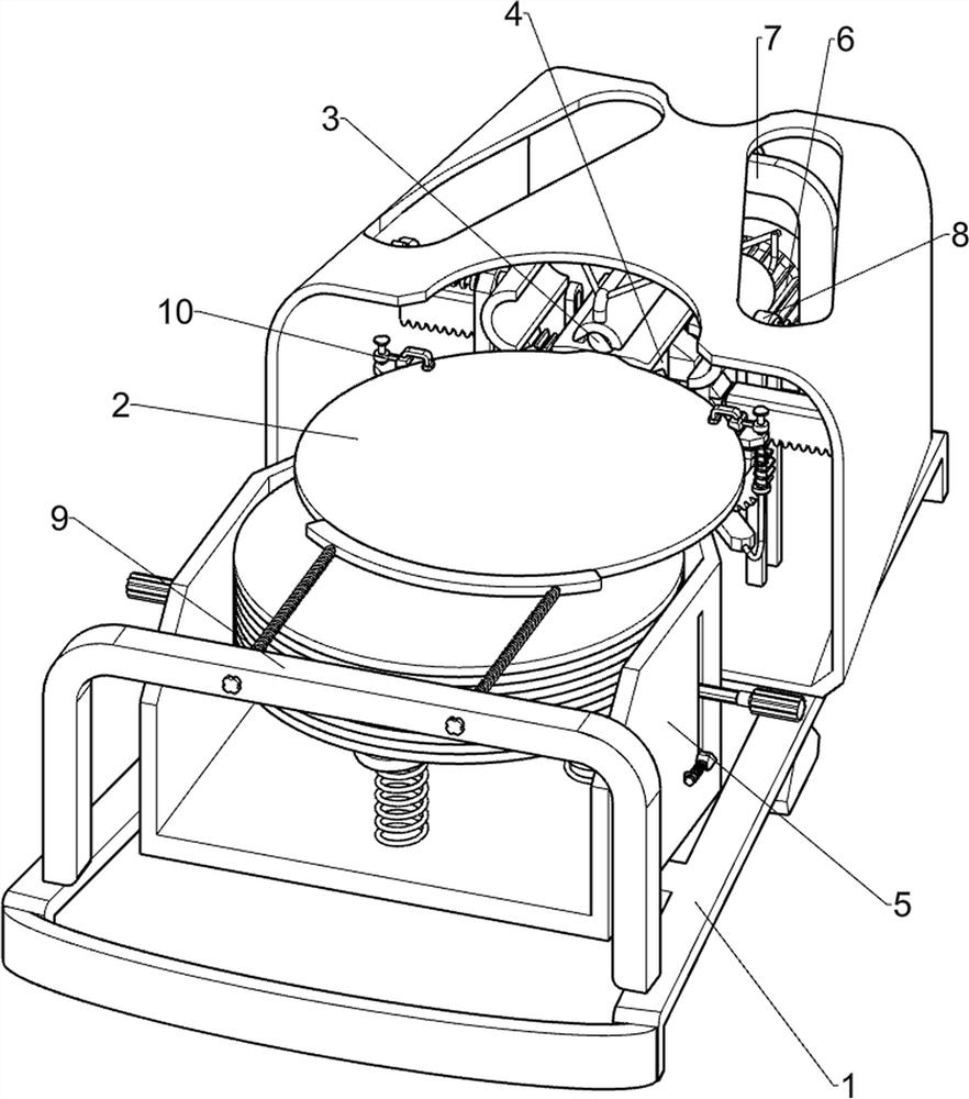
[0026] A kind of iron pan raw material handle making equipment, such as figure 1 , figure 2 , image 3 and Figure 4 As shown, it includes a base 1, an iron pan plate 2, an extruding rod 3, a first extruding plate 4, a bearing mechanism 5, a driving mechanism 6 and a push-out mechanism 7. The left side of the base 1 is provided with a bearing mechanism 5, and the bearing mechanism 5 An iron pan plate 2 is placed on the upper part, a driving mechanism 6 is arranged in the middle of the right side of the base 1, a first extruding plate 4 is arranged on the left side of the driving mechanism 6, a push-out mechanism 7 is arranged on the right side of the base 1, and a push-out mechanism 7 is arranged on the left side of the push-out mechanism 7. Squeeze rod 3.

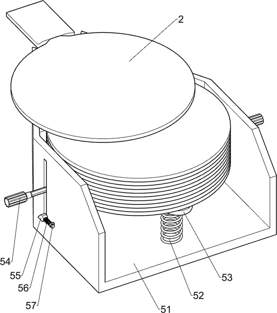
[0027] The bearing mechanism 5 includes a bearing frame 51, a first spring 52, a support plate 53, a handle 54, a first inclined block 55, a second spring 56, a first guide rod 57 and a first mounting block 58, and the...

Embodiment 2

[0032] On the basis of Example 1, such as Figure 5 , Figure 6 and Figure 7 Shown, also comprise extruding mechanism 8, extruding mechanism 8 includes second rotating rod 81, second support frame 82, first gear 83, second ratchet rack 84, spur rack 85, stop bar 86, The fourth spring 87, the second guide rod 88 and the second extruding plate 89, the front and rear symmetrical rotation of the bearing frame 51 right side is provided with the second rotating rod 81, and the second rotating rod 81 is connected with the first rotating mounting block 58 , the right side of the base 1 is provided with a second support frame 82 symmetrically front and back, the second rotating rod 81 is provided with a first gear 83, the first gear 83 on the front side is located in the middle of the second rotating rod 81, and the first gear 83 on the rear side is The gear 83 is positioned at the right side of the second rotating rod 81, the first ratchet bar 64 outside is provided with a second r...


PUM


Abstract

The invention relates to handle manufacturing equipment, in particular to iron pan raw material handle manufacturing equipment. According to the iron pan raw material handle manufacturing equipment, automatic extrusion can be achieved, the bending degree is consistent, and automatic discharging can be achieved. According to the technical scheme, the iron pan raw material handle manufacturing equipment comprises a base, an iron pan plate, an extrusion rod, a first extrusion plate, a bearing mechanism, a driving mechanism and a push-out mechanism; the bearing mechanism is arranged on one side of the base; the iron pan plate is placed at the upper part of the bearing mechanism; the driving mechanism is arranged in the middle of one side of the base; the first extrusion plate is arranged on one side of the driving mechanism; the push-out mechanism is arranged on one side of the base; and the extrusion rod is arranged on one side of the push-out mechanism. According to the device, the effects of automatic extrusion, consistent bending and automatic discharging can be achieved.

Description

technical field [0001] The invention relates to a device for making a handle, in particular to a device for making a raw material handle of an iron pan. Background technique [0002] Iron pans are kitchen utensils that people use when cooking food. Generally, iron pans do not contain toxic substances, but some iron pans will oxidize when exposed to water. After the human body absorbs too much iron oxide, it will cause harm to the liver. The main The composition is iron, and a small amount of sulfur, silicon, phosphorus and other substances are added to make it. [0003] However, in the prior art, when manufacturing iron pan handles, it is necessary to manually bend the handle after heating the handle, and then beat the handle after bending, resulting in irregular curvature of the manufactured handle, and manual blanking after the equipment is manufactured , During the operation of the equipment, direct contact with the equipment will cause people to be injured and affect th...

Claims


Application Information

Patent Timeline
Patent Type & Authority Applications(China)
IPC IPC(8): B21D45/02B21D11/10B21D11/22B21D43/00
CPCB21D45/02B21D11/10B21D11/22B21D43/003
Inventor 胡锦森
Owner 胡锦森
Why Eureka
Try Eureka