Electric hysterectomy device and assembling method thereof

A hysterectomy, electric technology, applied in surgical forceps, surgical cutting instruments, medical science and other directions, can solve problems such as affecting the doctor's field of vision, increasing patient damage, difficult to absorb blood, etc., achieving convenient synchronization or separate control, ensuring connection and Positioning effect, the effect of improving cutting safety

Pending Publication Date: 2022-03-08
ZHEJIANG SHENDASIAO MEDICAL INSTR
View PDF1 Cites 0 Cited by
  • Summary
  • Abstract
  • Description
  • Claims
  • Application Information

AI Technical Summary

Problems solved by technology

[0003] However, there are certain defects in the actual use of the electric hysterectomy device. One is that the cutting head of the cutting knife tube needs to be exposed to the outside of the puncture sleeve when rotating and cutting, so it is easy to interact with external organs during its rotation. contact, causing damage to external organs
The second is that a large amount of blood will be sprayed out during the cutting process, causing the blood to accumulate around the knife head and affect the doctor's field of vision
The current solution to this problem i

Method used


Image

  • Electric hysterectomy device and assembling method thereof
  • Electric hysterectomy device and assembling method thereof
  • Electric hysterectomy device and assembling method thereof

Examples


Embodiment Construction

[0028] The present invention will be further described below in conjunction with the accompanying drawings and embodiments, but not as a basis for limiting the present invention.

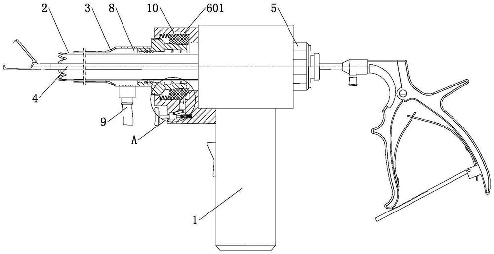
[0029] Example. An electric hysterectomy device, constituted as figure 1 As shown, it includes an electric handle 1, the electric handle 1 is rotated and connected with a cutting knife tube 2, the end of the cutting knife tube 2 is provided with a toothed cutter head, and the inner side of the cutting knife tube 2 is provided with a uterine grasping forceps 4. The outer side of the excision knife tube 2 is covered with a suction tube 3, and the outside of the suction tube 3 can be provided with a puncture sleeve. The engaging part that the driving part 5 cooperates with, the engaging part and the driving part 5 are existing engaging driving structures for the resection knife tube 2, and the other end of the electric handle 1 is slidably connected with an adapter ring 6, and the adapter ring 6 The ...


PUM


Abstract

The invention discloses an electric hysterectomy device and an assembling method thereof.The electric hysterectomy device comprises an electric handle (1), an excision knife tube (2) is rotationally connected to the electric handle (1), uterus grasping forceps (4) are arranged on the inner side of the excision knife tube (2), a suction tube (3) is arranged on the outer side of the excision knife tube (2) in a sleeving mode, one end of the electric handle (1) is connected with the excision knife tube (2) through a driving part (5), and the other end of the electric handle (1) is connected with the uterus grasping forceps (4). The other end of the electric handle (1) is connected with an adapter ring (6) in a sliding mode, the end of the adapter ring (6) extends to the outer side of the electric handle (1) and is connected with a suction pipe (3), one side of the adapter ring (6) is connected with an operation button (7) located on the electric handle (1) through a transmission assembly, a liquid suction channel (8) is formed between the suction pipe (3) and the resection knife pipe (2), and one end of the liquid suction channel (8) is connected with a liquid suction pipe (9). According to the invention, the excision knife tube can be effectively prevented from being in contact with an external organ during excision operation, and hematocele suction of an excision part can be realized.

Description

technical field [0001] The invention relates to an electric hysterectomy device, in particular to an electric hysterectomy device and an assembly method thereof. Background technique [0002] In women's hysterectomy, it is often necessary to use a hysterectomy device to remove tissue in the uterus. The currently commonly used electric hysterectomy device is described in the patent 201922470627.4 "An electric hysterectomy device", which includes an electric handle connected to each other, a cutting knife tube, a puncture sleeve and a uterine grasping forceps. The working channel is established, and then the uterine grasping forceps pass through the resection knife tube and grab the tissue in the uterus. After grasping, the uterine grasper contacts the tissue with the cutting head of the resection knife tube, and then turns on the electric handle to drive the resection knife The tube rotates at a high speed in the working channel and cuts the tissue, so that the tissue and th...

Claims


Application Information

Patent Timeline
IPC IPC(8): A61B17/42A61B17/3205A61B17/295
CPCA61B17/42A61B17/4241A61B17/3205A61B17/295A61B2017/4216A61B2217/005
Inventor 申屠琛
Owner ZHEJIANG SHENDASIAO MEDICAL INSTR
Why Eureka
Try Eureka