
High-efficiency and high-brightness light path transmission method and optical mechanism

An optical mechanism and high-brightness technology, applied in the field of optical applications, can solve the problems of energy loss, dark imaging brightness, etc., and achieve the effects of reducing light energy loss, improving utilization, and improving clarity

Pending Publication Date: 2022-03-04
上海首镜科技有限公司
View PDF0 Cites 0 Cited by
  • Summary
  • Abstract
  • Description
  • Claims
  • Application Information

AI Technical Summary

Problems solved by technology

[0004] However, in actual experience, energy loss is inevitable in the transmission of the target beam in the combined optical path, and the brightness of the image is dim

Method used


Image

  • High-efficiency and high-brightness light path transmission method and optical mechanism
  • High-efficiency and high-brightness light path transmission method and optical mechanism

Examples


Embodiment Construction

[0033] In order to make the technical means, creative features, goals and effects achieved by the present invention easy to understand, the following embodiments will specifically describe an efficient and bright optical path transmission method and optical mechanism of the present invention in conjunction with the accompanying drawings. It should be noted that, The descriptions of these embodiments are used to help the understanding of the present invention, but are not intended to limit the present invention.

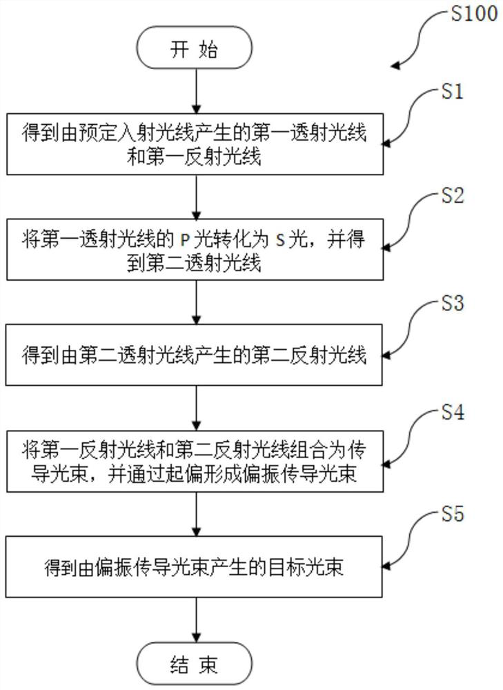
[0034] Such as figure 1 As shown, an efficient and bright optical path transmission method S100 in this embodiment includes the following steps:

[0035] Step S1: Perform polarization splitting on predetermined incident light to obtain first transmitted light and first reflected light.

[0036] Specifically, this step is achieved through a PBS membrane.

[0037] Step S2: converting the P light of the first transmitted light into the S light of the first transmitted ...


PUM


Abstract

The invention belongs to the field of optical application, and discloses a high-efficiency and high-brightness light path transmission method, which can greatly reduce the energy loss of a target light beam in a transmission process so as to remarkably improve the utilization rate of initial incident light energy and the illumination brightness. The first transmission P polarized light and the first reflection S polarized light are formed by polarizing and splitting preset incident light; then, the P polarized light of the first transmission light is converted into second transmission S polarized light, the second transmission S polarized light is reflected to obtain second reflection light, in light path conduction of light obtained from the preset incident light, all the light is converted into the first reflection S polarized light and the second reflection S polarized light, and light energy loss caused by the P light in the conduction process is greatly reduced. The invention further discloses an optical mechanism of the high-efficiency and high-brightness light path for implementing the high-efficiency and high-brightness light path transmission method. The optical mechanism comprises a polarization conversion prism group, a preset PBS film, a half-wave plate, a preset polaroid and a preset PBS prism.

Description

technical field [0001] The invention belongs to the field of optical applications, and in particular relates to an efficient and bright optical path transmission method and an optical mechanism. Background technique [0002] LcoS display technology is a display technology based on silicon-based CMOS integrated circuit technology, which uses reflection of external light to achieve imaging. Compared with other display technologies, it has high resolution, requires fewer peripheral ICs, and module packaging Due to its low cost and high utilization of light, it is widely used in many related fields, and AR display is one of the important directions in these fields. [0003] At present, the optical components in the LcoS package of AR are light source and prism / reflector, and the optical path formed by the combination is used to form the target beam required for imaging. [0004] However, in actual experience, the transmission of the target beam in the combined optical path stil...

Claims


Application Information

Patent Timeline
Patent Type & Authority Applications(China)
IPC IPC(8): G02B27/01G02B27/28
CPCG02B27/0101G02B27/283G02B27/286G02B2027/0118
Inventor 田永明胡挺
Owner 上海首镜科技有限公司
Learn More