
Interferometer based on continuous rotation and working method thereof

A technology of interferometer and rotating arm, which is applied in the field of interferometer, can solve the problems of low transmittance and low overall transmittance, and achieve the effect of fast scanning speed, improved signal-to-noise ratio, and increased luminous flux

Pending Publication Date: 2022-03-04
HANGZHOU PUYU TECH DEV CO LTD
View PDF4 Cites 0 Cited by
  • Summary
  • Abstract
  • Description
  • Claims
  • Application Information

AI Technical Summary

Problems solved by technology

This technology has a fast scanning speed, but because the scanned device uses the principle of refraction, the light needs to pass through an infrared-transparent medium, and the thickness of the medium determines the maximum resolution of the instrument
Therefore, this method has the problem that the overall transmittance is low, and the higher the resolution, the lower the transmittance.

Method used


Image

  • Interferometer based on continuous rotation and working method thereof

Examples


Embodiment 1

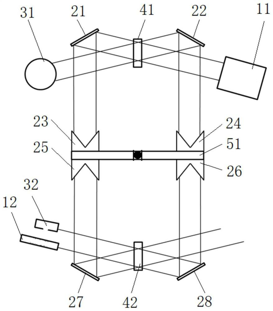
[0027] figure 1 A schematic structural diagram of an interferometer based on continuous rotation according to an embodiment of the present invention is given, as figure 1 As shown, the interferometer based on continuous rotation includes:

[0028] A first light source 11, a first mirror 41 and a first detector 31, the first light source 11 is used to emit measurement light;

[0029] The first reflector 21 and the second reflector 22, the first reflector 21 and the second reflector 22 are arranged symmetrically about the first lens 41, the first reflector 21 is used to reflect the measurement The transmitted light of the light passing through the first mirror 41, the second mirror 22 is used to reflect the reflected light of the measurement light on the first mirror 41;

[0030] The first reflection unit, the first reflection unit includes:

[0031] a first rotating arm 51 and a driving unit, the first rotating arm 51 is driven to rotate around a rotating shaft by the drivin...

Embodiment 2

[0049] An application example of the continuous rotation-based interferometer and its working method according to Embodiment 1 of the present invention.

[0050] In this application example, if figure 1 As shown, the third-sixth reflectors on the first rotating arm 51 are corner reflectors, and the second light source 12 is a laser.

[0051] According to the working method based on the continuously rotating interferometer according to the embodiment of the present invention, the working method is:

[0052] The drive unit drives the first rotating arm 51 to continuously rotate in one direction such as counterclockwise, the third reflector 23 and the fourth reflector 24 follow the rotation of the first rotating arm 51, and at the same time, the first light source 11 emits a measurement light, the second light source 12 emits reference light;

[0053] The third reflector 23 and the fourth reflector 24 periodically rotate to the first working position. At this time, the reflecte...

Embodiment 3

[0059] The application example of the interferometer based on continuous rotation and its working method according to Embodiment 1 of the present invention is different from Embodiment 2 in that:

[0060] A second reflection unit is also provided. The second reflection unit is the same as the first reflection unit and shares a rotation axis. The angle between the first rotating arm and the second rotating arm is 90 degrees, which further improves the scanning speed.


PUM


Abstract

The invention provides an interferometer based on continuous rotation and a working method thereof, the interferometer based on continuous rotation comprises a first light source, a first transflective mirror and a first detector, the first light source is used for emitting measuring light; the first reflecting mirror and the second reflecting mirror are symmetrically arranged relative to the first transflective mirror, the first reflecting mirror is used for reflecting transmission light, penetrating through the first transflective mirror, of the measuring light, and the second reflecting mirror is used for reflecting reflected light, on the first transflective mirror, of the measuring light; the first reflecting unit comprises a first rotating arm rotating around a rotating shaft; the third reflecting mirror and the fourth reflecting mirror are respectively arranged on the first rotating arm and are symmetrical about the rotating shaft; when the third reflecting mirror and the fourth reflecting mirror rotate to the first working position, the third reflecting mirror is used for reflecting reflected light on the first reflecting mirror back to the first reflecting mirror, and the fourth reflecting mirror is used for reflecting reflected light on the second reflecting mirror back to the second reflecting mirror. The method has the advantages of high scanning speed, high signal-to-noise ratio and the like.

Description

technical field [0001] The invention relates to an interferometer, in particular to an interferometer based on continuous rotation and its working method. Background technique [0002] Interferometers are widely used in spectral measurements, including infrared, visible and ultraviolet spectra, and are widely used in scientific research, industrial processes, satellite remote sensing, environmental monitoring and other industries. [0003] The interferometer can modulate the incident light to form an interference spectrum, and combined with a suitable sampling method and Fourier transform, the spectrum can be collected. The Fourier transform spectroscopy with the interferometer as the core has the characteristics of large luminous flux, adjustable resolution, and high wave number accuracy. Interferometers themselves, on the other hand, are precision optical machines with moving parts -- moving mirrors. The moving mirror needs to keep moving at a constant speed as much as p...

Claims


Application Information

Patent Timeline
Patent Type & Authority Applications(China)
IPC IPC(8): G01J3/02G01J3/45
CPCG01J3/0202G01J3/0205G01J3/45
Inventor 向俊杰喻正宁李锐俞晓峰吴锋明韩双来
Owner HANGZHOU PUYU TECH DEV CO LTD
Learn More