
Spatial light-optical fiber coupling device and method based on visual detection

An optical fiber coupling device and space light technology, which is applied in the coupling of optical waveguides, light guides, optics, etc., can solve the problems of slow speed, low efficiency, and cannot be fully automatically realized, and achieve the effect of improving the coupling optical power and automatic and rapid adjustment.

Active Publication Date: 2022-03-01
PENG CHENG LAB
View PDF6 Cites 2 Cited by
  • Summary
  • Abstract
  • Description
  • Claims
  • Application Information

AI Technical Summary

Problems solved by technology

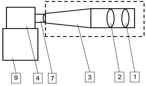
[0006] The main purpose of the present invention is to provide a spatial light-fiber coupling device and method based on visual detection, aiming to solve the problem of low efficiency, slow speed and inability to fully automatically realize coupling from spatial light to single-mode fiber in the prior art question

Method used


Image

  • Spatial light-optical fiber coupling device and method based on visual detection
  • Spatial light-optical fiber coupling device and method based on visual detection
  • Spatial light-optical fiber coupling device and method based on visual detection

Examples


Embodiment Construction

[0045] In order to make the object, technical solution and effect of the present invention more clear and definite, the present invention will be further described in detail below with reference to the accompanying drawings and examples. It should be understood that the specific embodiments described here are only used to explain the present invention, not to limit the present invention.

[0046] Those skilled in the art will understand that unless otherwise stated, the singular forms "a", "an", "said" and "the" used herein may also include plural forms. It should be further understood that the word "comprising" used in the description of the present invention refers to the presence of said features, integers, steps, operations, elements and / or components, but does not exclude the presence or addition of one or more other features, Integers, steps, operations, elements, components, and / or groups thereof. It will be understood that when an element is referred to as being "conn...


PUM


Abstract

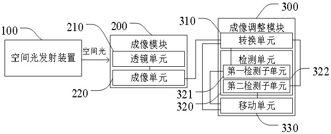
The invention discloses a spatial light-optical fiber coupling device and method based on visual detection. The device comprises an imaging module and an imaging adjustment module, the imaging module is used for carrying out coupling imaging on the spatial light emitted by the spatial light emitting device to obtain a first imaging picture and transmitting the coupled spatial light to the imaging adjustment module, and the imaging adjustment module is used for generating a second imaging picture after obtaining the first imaging picture and carrying out position adjustment on the second imaging picture to generate a third imaging picture; meanwhile, the adjustment parameters are obtained and then sent to the imaging module, and the imaging module is further used for conducting imaging adjustment on the first imaging picture according to the adjustment parameters. After the first imaging picture is obtained through the imaging adjustment module, the second imaging picture is generated, and the second imaging picture is adjusted to obtain the adjustment parameter, so that the imaging module performs imaging adjustment on the first imaging picture according to the adjustment parameter, the maximum coupling light power can be obtained when the spatial light is coupled to the optical fiber, and the optical fiber coupling efficiency is automatically adjusted.

Description

technical field [0001] The invention relates to the technical field of space laser communication, in particular to a space light-fiber coupling device and method based on vision detection. Background technique [0002] Compared with microwave communication, laser communication has extremely high potential communication data rate (greater than tens of gigabits per second or even higher), and the size, quality and power consumption of communication terminals are small. In China, a large number of universities and research institutes have developed Research on laser communication technologies such as satellite-ground, inter-satellite, and free space. Space light-single-mode fiber coupling technology is one of the key technologies in space laser communication, and its coupling efficiency seriously affects the quality of laser communication. [0003] In the real scene, when the space laser is transmitted to the communication terminal through the space channel, the beam spot diame...

Claims


Application Information

Patent Timeline
Patent Type & Authority Applications(China)
IPC IPC(8): G02B6/42
CPCG02B6/4287G02B6/4206
Inventor 温林凯张轶群薛佳音张钦宇王伟志王昌伟
Owner PENG CHENG LAB
Learn More